


POWER WAVE® / POWER FEED
WIRE FEEDER
INTERCONNECTIONS
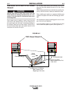
Connect the control cable between the power source
and wire feeder. The wire feeder connection on the
robotic Power Waves® is located under the spring
loaded output cover, near the bottom of the case front.
The control cable is keyed and polarized to prevent
improper connect.
For convenience sake, the electrode and control
cables can be routed behind the left or right strain
reliefs (under the spring loaded output cover), and
along the channels formed into the base of the Power
Wave®, out the back of the channels, and then to the
wire feeder.
Output connections on some Power Waves® are
made via 1/2-13 threaded output studs located
beneath the spring loaded output cover at the bottom
of the case front. On machines which carry the CE
mark, output connections are made via Twist-Mate
receptacles, which also located beneath the spring
loaded output cover at the bottom of the case front.
A work lead must be run from the negative (-) power
source output connection to the work piece. The work
piece connection must be firm and secure, especially
if pulse welding is planned.
Excessive voltage drops at the work piece con-
nection often result in unsatisfactory pulse weld-
ing performance.
------------------------------------------------------------------------
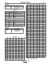
CONTROL CABLE SPECIFICATIONS
It is recommended that genuine Lincoln control cables
be used at all times. Lincoln cables are specifically
designed for the communication and power needs of
the Power Wave® / Power Feed™ system.
The use of non-standard cables, especially in
lengths greater than 25 ft(.m), can lead to commu-
nication problems (system shutdowns), poor
motor acceleration (poor arc starting) and low
wire driving force (wire feeding problems).
------------------------------------------------------------------------
Lincoln control cables are copper 22 conductor cable
in a SO-type rubber jacket.
CAUTION
CAUTION
Work Voltage Sensing
The Power Wave® s are shipped from the factory with
the work sense lead enabled.
For processes requiring work voltage sensing, con-
nect the (21) work voltage sense lead from the Power
Wave® to the work. Attach the sense lead to the work
as close to the weld as practical. Enable the work
voltage sensing in the Power Wave® as follows:
ELECTRIC SHOCK can kill.
• Do not touch electrically live parts
or electrodes with your skin or wet
clothing.
• Insulate yourself from the work and ground.
• Always wear dry insulating gloves.
------------------------------------------------------------------------
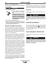
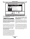
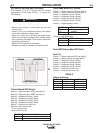
1. Turn off power to the power source at the discon-
nect switch.
2. Remove the front cover from the power source.
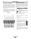
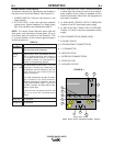
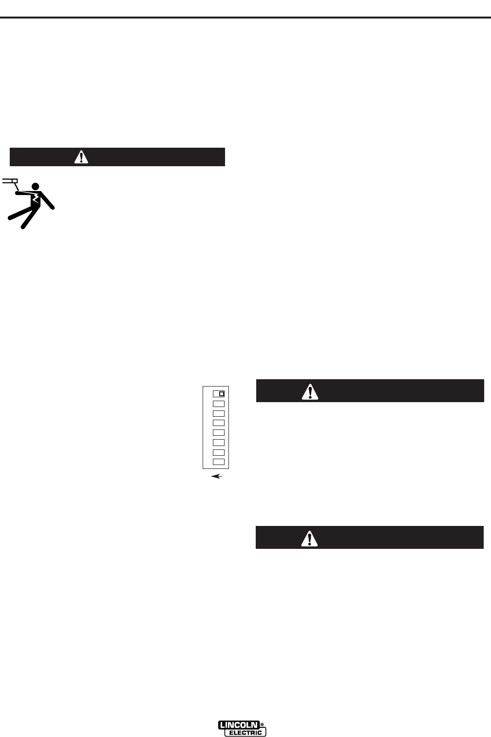
3. The control board is on the left side of the power
source. Locate the 8-position DIP
switch and look for switch 8 of the DIP
switch.
4. Using a pencil or other small object,
slide the switch right to the OFF position
if the work sense lead is NOT connect-
ed. Conversely, slide the switch left to
the ON position if the work sense lead is
present.
5. Replace the cover and screws. The PC board will
(read) the switch at power up, and configure the
work voltage sense lead appropriately.
Electrode Voltage Sensing
Enabling or disabling electrode voltage sensing is
automatically configured through software. The 67
electrode sense lead must be connected at the wire
feeder.
A-7
INSTALLATION
POWER WAVE® 655/R
A-7
WARNING
O
N
1 2 3 4 5 6 7 8