


HIGH SPEED GEAR BOX
Changing the ratio requires a gear change and a PC
board switch change. The Power Feed Wire Feeders
are shipped with both high speed and a low speed
gears. As shipped from the factory, the low speed
(high torque) gear is installed on the feeder. To
change Gear ratio see Power Feed 10/R Instruction
Manual.
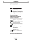
ELECTRIC SHOCK can kill.
• Do not touch electrically live parts or
electrodes with your skin or wet
clothing.
• Insulate yourself from the work and
ground.
• Always wear dry insulating gloves.
-------------------------------------------------------------
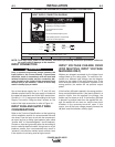
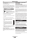
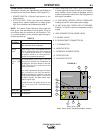
1. Set the High/Low switch code on Wire Drive PC
board as follows:
• Turn off power to the power source at the discon-
nect switch.
• Remove the front cover from the power source.
• The wire feed head board is on the right
side of the power source. Locate the 8-
position DIP switch and look for position
8 of the DIP switch.
• Using a pencil or other small object,
slide the switch right to the OFF posi-
tion, when the low speed gear is
installed. Conversely, slide the switch
left to the ON position when the high
speed gear is installed.
• Replace the cover and screws. The PC board will
“read” the switch at power up, automatically
adjusting all control parameters for the speed
range selected.
O
N
1 2 3 4 5 6 7 8
WARNING
A-8
INSTALLATION
POWER WAVE® 655/R
A-8
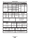
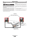
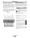
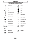
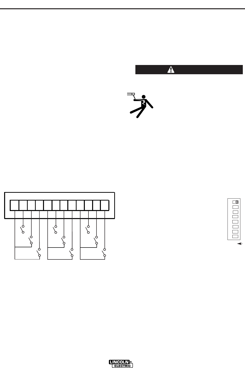
EXTERNAL I/O CONNECTOR
The Power Wave® is equipped with a port for making
simple input signal connections. The port is divided
into three groups: Trigger group, Cold Inch Group and
Shutdown Group. Because the Power Wave® is a
‘slave’ on the DeviceNet network, the Trigger and
Cold Inch Groups are disabled when the DeviceNet /
Gateway is active.
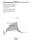
The shutdown group is always enabled. Shutdown 2
is used for signaling low flow in the water cooler.
Unused shutdowns must be jumpered. Machines from
the factory come with the shutdowns already
jumpered.(See Figure A.5)
D
E
F
1
2
3
4
5
6
78
910
11
12
G
H
I
A
B
C
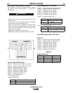
+15 VDC for Trigger Group
Trigger Input
Dual Procedure Input
4 Step Input
+15 VDC for Cold Inch Group
Cold Inch Forward
Cold Inch Reverse
Gas Purge Input
+15 for shutdown group
Shutdown1 input
Shutdown2 input (Water Fault)
Reserved for future use
FIGURE A.5