


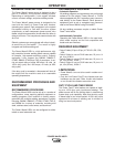
VOLTAGE SENSING
The best arc performance occurs when the Power
Wave® s has accurate data about the arc conditions.
Depending upon the process, inductance within the
electrode and work lead cables can influence the volt-
age apparent at the contact tip. Voltage sense leads
improve the accuracy of the arc conditions and can
have a dramatic effect on performance.
If the voltage sensing is enabled but the sense
leads are missing or improperly connected,
extremely high welding outputs may occur.
Do not tightly bundle the work sense lead to the work
lead.
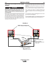
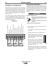
The ELECTRODE sense lead (67) is built into the
K1795 control cable. The WORK sense lead (21) con-
nects to the Power Wave® at the four-pin connector
located underneath the output stud cover.
Enable the voltage sense leads as follows:
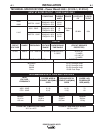
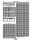
TABLE 2
Process Electrode Voltage Work Voltage
Sensing 67 lead * Sensing 21 lead
GMAW 67 lead required 21 lead optional**
GMAW-P
67 lead required 21 lead optional**
FCAW 67 lead required 21 lead optional**
GTAW
Voltage sense at studs Voltage sense at studs
SAW 67 lead required 21 lead optional**
* The electrode voltage 67 sense lead is part of the
control cable to the wire feeder.
** For consistent weld quality, work voltage sensing is
recommended.
CAUTION
A-6
INSTALLATION
POWER WAVE® 655/R
A-6
When negative electrode polarity is required, such as
in some Innershield applications, reverse the output
connections at the power source (electrode cable to
the negative (-) stud, and work cable to the positive
(+) stud).
When operating with electrode polarity negative the
switch 7 must be set to ON on the Wire Feed Head
PC Board. The default setting of the switch is OFF to
represent positive electrode polarity.
Set the Negative Polarity switch on Wire Feed Head
PC board as follows:
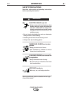
ELECTRIC SHOCK can kill.
• Do not touch electrically live parts
or electrodes with your skin or wet
clothing.
• Insulate yourself from the work and
ground.
• Always wear dry insulating gloves.
------------------------------------------------------------------------
1. Turn off power to the power source at the discon-
nect switch.
2. Remove the front cover from the power source.
3. The wire feed head board is on the right side of the
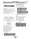
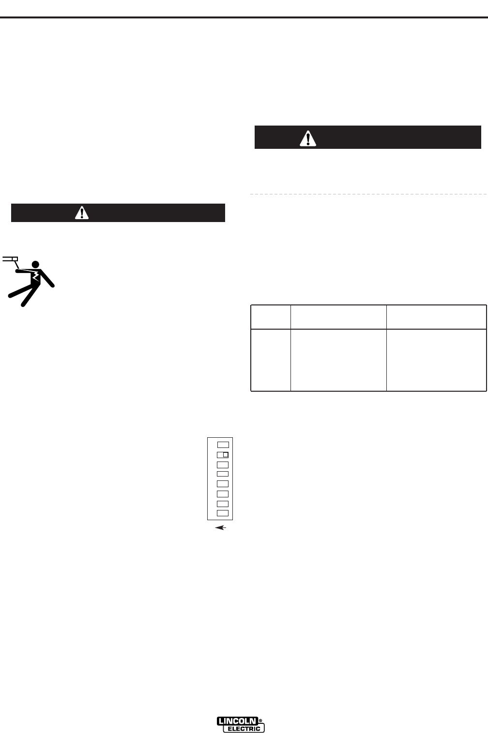
power source. Locate the 8-position DIP switch and
look for switch 7 of the DIP switch.
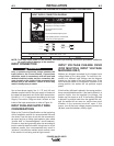
4. Using a pencil or other small object, slide
the switch right to the OFF position for
positive electrode polarity. Conversely,
slide the switch left to the on position for
negative electrode polarity.
5. Replace the cover and screws. The PC
board will “read” the switch at power up,
and configure the work voltage sense lead appro-
priately.
WARNING
O
N
1 2 3 4 5 6 7 8