


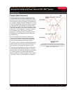


Making Fillet Welds with Power Wave AC/DC 1000™ System
The future of welding is here.
®
APPLICATION
3/10
Welding Guide
WAVEFORM CONTROL TECHNOLOGY
TM
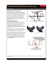
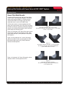
Square Wave vs. Sine Wave
Figure 2 shows one cycle of a true 60 Hz sine wave
with a square wave superimposed upon it. Note that
while the rms
2
value and the peak values are the same
for both waves, the transition time for peak-to-peak is
much shorter for the square wave. The transition
period is what has always caused instability with
conventional AC welding but with the rapid transition
associated with the Power Wave AC/DC 1000™, arc
stability is increased.
Square Wave Balance
Square wave balance can allow the arc to act more
as a DC negative or DC positive arc, thus increasing
deposition rate or increasing penetration. This is
always expressed as a percentage of the DC +
component. i.e., (25% Balance means that only 25%
of the cycle will be positive while 75% of the cycle will
be negative, etc.)
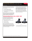
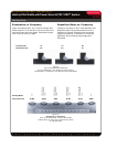
Figure 3 shows two 3/8” (10mm) flat positioned fillet
welds. Both were made at 814 amperes but the square
wave AC 25% balance wave is made 17% faster.
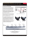
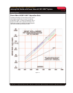
Figure 4 graphically shows the significance that square
wave balance can and does play. Note that only 25%
of the time is the arc positive while 75% of the time
it is negative. This flexibility can be used to tailor the
arc to achieve best results by increasing deposition,
decreasing penetration or decreasing deposition and
increasing penetration.
Figure 4
Figure 3
DC+ AC 25% Balanced
1 CYCLE
1/60 SECOND
SINE WAVE
TRANSITION
REGION
SQUARE WAVE
TRANSITION
REGION
0
+ VOLTS
- VOLTS
60 Hz SINE WAVE vs 60 Hz SQUARE WAVE
Figure 2
2
Rms: root-mean-square value of current or voltage. For example, when someone refers to, “110 volts,” this is actually an rms value as is
“30 volts AC”, etc.