


Making Fillet Welds with Power Wave AC/DC 1000™ System
The future of welding is here.
®
APPLICATION
4/10
Welding Guide
WAVEFORM CONTROL TECHNOLOGY
TM
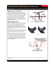
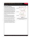
Square Wave Offset Effect
Offset is expressed as a percentage between -25%
and +25% of the rms
2
value that is kept positive or
negative. In other words, -25% means the normal
positive component of each cycle is held to 25% of
the normal rms value and the negative component
becomes 75%. In some respects, when offset is
adjusted to maximum values, the arc action almost
becomes analogous to that of a pulsed arc. Negative
values contribute to increasing deposition to levels
closely approaching the values obtainable with DC
negative welding. See Figure 5.
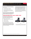
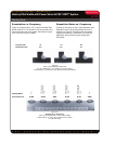
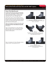
Figure 6 shows two welds: the same 3/8” (10mm) flat
position fillet as Figure 3, but this time made using a
setting of 25% balance, (-)10% offset. Note that this
results in an additional gain of 12% in travel speed!
This is a net gain of 29% over DC+.
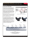
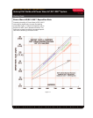
The increased deposits possible using a combination
of wave balance and wave offset may raise the
question about root penetration. While at present the
major welding codes do not allow sizing a fillet weld
based on root penetration, some producers of
proprietary products do. Figure 7 shows the depth of
penetration as compared to DC+ for a number of
settings. This shows a variation of only .05” (1.3mm) in
penetration, a variation of nine to ten percent. All of
the welds were made when the plate was at room
temperature and at 54.25Kj heat input.
Figure 7
Penetration vs. Various Modes
All welds made using 5/32” (4mm) Diameter Electrode
525 Amperes, 31 Volts, 1.25” (31.8mm) ESO
18 ipm (457.2mm/min) Travel Speed
54.25 Kj Heat Input
Penetration-mm 5.53 4.06 4.06 4.02 4.43
Square Wave
Balanced
SW AC
25% Balanced
SW AC
25% Balanced
(-) 10% Offset
SW AC
25% Balanced
(-) 20% Offset
Mode
DC+
1 CYCLE
1/60 SECOND
50% Negative
50% Positive
0
Total
Amps
Total
Amps
Square Wave - Normal Curve
Square Wave - Negative Offset
Square Wave - Current Offset
Figure 5
Comparison of offset vs normal balanced wave
Figure 6
DC+ SW AC with Offset
AC 25% Balance
(-)10% Offset