


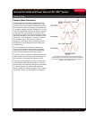
Making Fillet Welds with Power Wave AC/DC 1000™ System
The future of welding is here.
®
APPLICATION
6/10
Welding Guide
WAVEFORM CONTROL TECHNOLOGY
TM
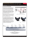
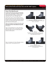
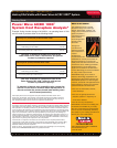
Figure 9
5/32” (4.0mm) Diameter Electrode
AC 25% Balanced, (-)10% Offset, Hz (shown above)
525 Amperes, 1.0 (25mm), 21 ipm (827mm/min) Travel Speed
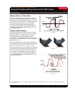
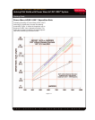
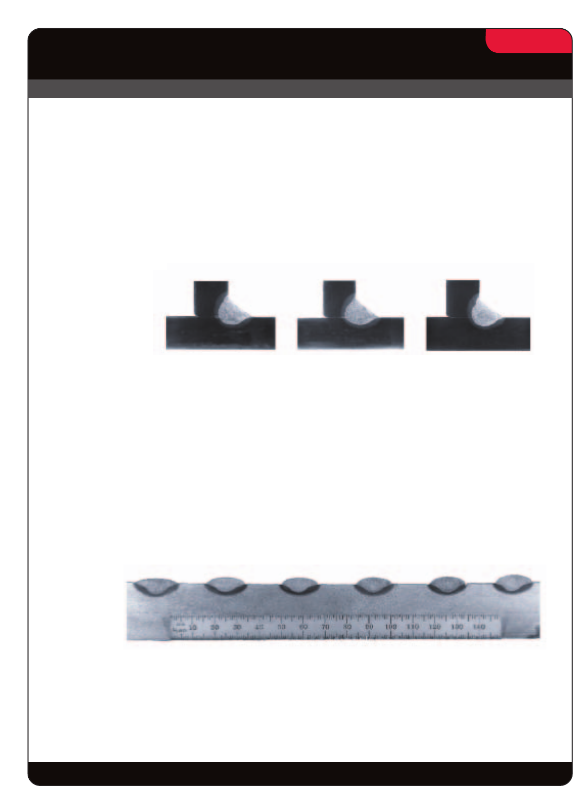
Figure 10
Penetration vs Frequency
5/32” (4.0mm) Electrode, 1.25” (31.8mm) ESO
526 Amperes, 31 Volts, 18 ipm (457mm/min) Travel
54.4 Kj Heat Input
Frequency-Hz
Penetration-mm
10
2.5
70
3.2
90
2.1
Penetration-mm
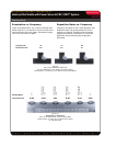
5.40 3.83 3.91 3.87 4.10 4.02
DC+
SW AC 25% BAL
(-) 10% OFFSET
40 Hz
SW AC 25% BAL
(-) 10% OFFSET
20 Hz
SW AC 25% BAL
(-) 10% OFFSET
70 Hz
SW AC 25% BAL
(-) 10% OFFSET
80 Hz
DC-
Welding Mode
Penetration vs. Frequency
Figure 9 compares three .31” (7.9mm) horizontal fillet
welds made at 10, 70 and 90 Hz. All were made at the
same heat input and travel speed. Penetration ranges
from 2.1mm to 3.2mm in depth.
Frequency also plays a role in total deposition rate.
Deposition rates may increase about 6% as the
frequency is lowered. Deposition rate decreases
slightly as frequency is increased. This could be
significant, when producing large single pass
fillet welds.
Deposition Rates vs. Frequency