


Making Fillet Welds with Power Wave AC/DC 1000™ System
The future of welding is here.
®
APPLICATION
9/10
Welding Guide
WAVEFORM CONTROL TECHNOLOGY
TM
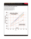
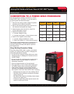
CONVERTING TO A POWER WAVE PROCEDURE
An easy approach to making a conversion to a Power
Wave AC/DC 1000™ procedure is to use this table as
a general guide and follow these steps:
1. Start with the existing variable voltage DC positive
procedure as the reference procedure.
2. Move to AC balanced square wave mode and use
the reference travel speed and voltage.
3. Adjust frequency from 30 to 90 Hz. (stop if the
current value begins to drop).
4. Shift the AC balance to 25%,
a. Increase voltage 2-3 volts,
b. Increase travel speed 1.2 times reference value.
5. Add 5 to 10% negative (minus) offset,
a. Increase voltage an additional 1-2 volts,
b. Raise travel speed to 1.3 times reference speed.
This will yield a good starting point for converting a DC+
fillet welding procedure. Fine tuning these steps will
yield the maximum increase with equal or improved
weld appearance.
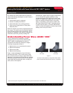
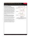
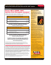
Easy Welding Procedure Setup
The Power Wave AC/DC 1000™ system is the easiest
system ever produced when it comes to changing from
one welding procedure to another.
• No need to move (change) welding cables even when
changing polarity or changing from constant current to
constant voltage.
• No need to internally reconnect power carrying taps or
bus bars, hence, in many instances no need for a
maintenance electrician.
• Control all output functions on the control panel.
• Fully supported by Lincoln’s Power Wave Submerged
Arc Utilities software where demanding applications
require activity reporting or even remote procedure
verification (see Nextweld NX3.20 brochure).The heart
of the system is the Power Wave AC/DC 1000™ featuring:
• Balanced input line-draw even when welding with AC.
• High 86% electrical efficiency contributes to keeping
energy charges low.
• 95% power factor assures minimizing excess ampere
draw from the supply lines.
• Continuous output rating 1000 amperes assures the
system is ready-to-go full time.
% Positive % Offset
Deposition
Rate
Arc Volt
Change
100 DC+ NA 1.0 Reference
50 0 1.11 +0
25 0 1.20 +3
25 -10 1.30 +4
0 DC- NA 1.35 +3