


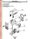
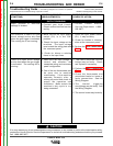

THEORY OF OPERATION
E-4E-4
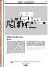
POWER MIG® 215
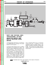
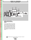
CONTROL BOARD, GUN
TRIGGER AND WIRE DRIVE
MOTOR
When the control board receives an activation
command from the trigger circuit the control
board supplies 12VDC which activates the gas
solenoid and output contactor. It also supplies
2 to 29 VDC (depending on the wire speed
setting) to the wire drive motor. The control
board monitors 0-5VDC signal from the wire
speed potentiometer and adjusts the motor
speed accordingly. The proper armature voltage
is then applied to the wire drive motor. The drive
motor speed is thus controlled which in turn
regulates the electrode wire feed speed through
the gun.
Two self re-setting thermostats are included in
the trigger circuitry. If either of these
thermostats would “open” due to excessive heat,
the trigger circuit would be interrupted and the
machine’s output and the wire feed would be
disabled. The board also contains overload
protection circuitry which protects the drive
motor from excessive current draw.
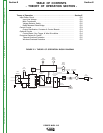
NOTE: Unshaded areas of block logic diagrams are the subject of discussion.
LINE
SWITCH
RECONNECT
PANEL
FAN
MOTOR
RECTIFIER
DIODE
BRIDGE
CONTROL BOARD
GAS
SOLENOID
WIRE
SPEED
CONTROL
WIRE
DRIVE
MOTOR
TACH
GUN TRIGGER
+
-
OUTPUT DIODE
BRIDGE
+
-
NEGATIVE
TERMINAL
CONTACTOR
CONTACTOR
CONTROL
TAP SELECTOR
SWITCH
OUTPUT
CHOKE
POSITIVE
TERMINAL
TRANSFORMER
THERMOSTAT
OUTPUT BRIDGE
THERMOSTAT
28 VAC
MAIN
TRANSFORMER
OUTPUT
CAPACITORS
GUN
ASSEMBLY
FIGURE E.4 – OPTIONAL CIRCUITS.
Return to Section TOC Return to Section TOC Return to Section TOC Return to Section TOC
Return to Master TOC Return to Master TOC Return to Master TOC Return to Master TOC