


TROUBLESHOOTING AND REPAIR
F-16F-16
POWER MIG® 215
WIRE DRIVE MOTOR AND WIRE SPEED POTENTIOMETER TEST
(continued)
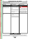
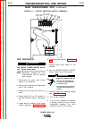
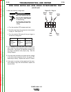
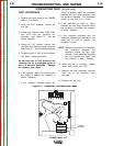
1. Make the following voltage tests:
a. Turn the machine OFF between each test.
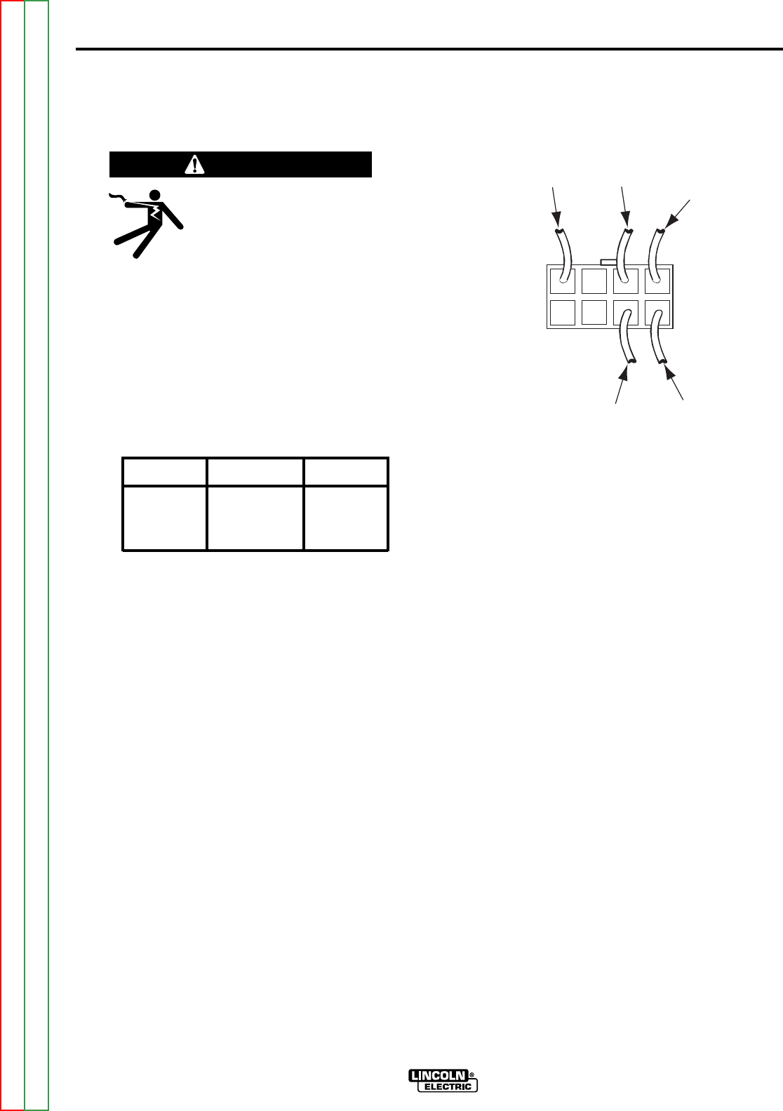
b. Carefully insert the meter probes into the lead side
of plug J4. See Figure F.4.
c. Turn the machine ON and pull the gun trigger to
conduct the voltage test.
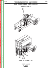
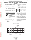
2. If the voltage to the wire drive motor armature is
zero, check the wires between plug J4 and the wire
drive motor. Also check the electrical connector J5
for proper connections and jumper plug. See the
Wiring Diagram.
3. If all wires and connectors are good and the voltage
to the drive motor armature is zero, the control PC
board may be faulty. Replace the control PC board.
4. If the motor is running at high speed and the arma-
ture voltage is high and uncontrollable, replace the
control board.
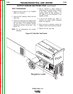
Figure F.4 - Plug J4
ELECTRIC SHOCK can kill.
• Do not touch electrically live
parts such as output terminals
or internal wiring.
• All input power must be electri-
cally disconnected before pro-
ceeding.
WARNING
FROM LEAD
FROM LEAD
FROM LEAD
Black
Armature
Lead
White
Armature
Lead
2-29 VDC
(varies depend-
ing on wire feed
speed)
Black
Tach
J11J11
Black
Arm
White
Arm
Blue
Tach
Red
Tach
Return to Section TOC Return to Section TOC Return to Section TOC Return to Section TOC
Return to Master TOC Return to Master TOC Return to Master TOC Return to Master TOC