


TROUBLESHOOTING AND REPAIR
F-17F-17
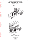
POWER MIG® 215
WIRE DRIVE MOTOR AND WIRE SPEED POTENTIOMETER TEST
(continued)
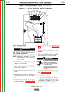
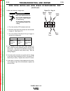
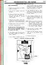
TEST FOR FEEDBACK VOLTAGE
TO CONTROL BOARD
1. Disconnect the main AC input power to
the machine.
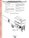
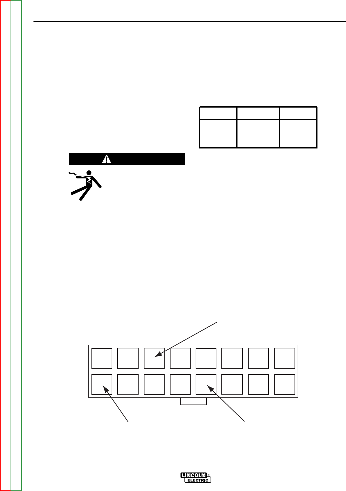
2. Locate plug J1 and the potentiometer
leads. See Figure F.5. #1113A and
1109A.
3. Connect main input power to the
machine.
4. Make the following voltage tests:
a. Turn the machine OFF between
each test.
b. Carefully insert the meter probes
into the lead side of plug J1. See
Figure F5.
c. Turn the machine ON and pull the
gun trigger to conduct the voltage
test.
5. If the 0 to 5 VDC is present, the
potentiometer circuit is sending the
correct feedback signal to the control
PC board. Check the leads and plug
J1. See the Wiring Diagram.
6. If the 0 to 5 VDC is NOT present or
NOT correct, the control PC board is
not receiving the proper feedback voltage
from the potentiometer circuit.
7. If the leads are okay, the potentiometer
circuit may be faulty, replace the
potentiometer circuit.
8. Replace the tool tray.
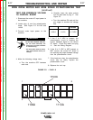
FROM LEAD
TO LEAD
EXPECTED
VOLTAGE
1109 A
1113 A
0 - 5 VDC
ELECTRIC SHOCK can kill.
• Do not touch electrically live
parts such as output terminals
or internal wiring.
• All input power must be electri-
cally disconnected before pro-
ceeding.
WARNING
1
9
8
16
1103A
1109A
1113A
FIGURE F.5. – PLUG J1
Return to Section TOC Return to Section TOC Return to Section TOC Return to Section TOC
Return to Master TOC Return to Master TOC Return to Master TOC Return to Master TOC