


P 7/ 10
Repair
[3] ASSEMBLING/ DISASSEMBLING
[3]-4. Trigger valve, Front cushion (cont.)
Refer to previous page and take the disassembling step in reverse.
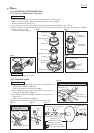
Note: Trigger valve case and Trigger guide have to be firmly inserted
into places until the click sounds can be heard.
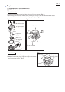
Trigger base section has to be assembled so that Lever can be put into
the center groove of Change rod.
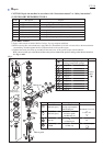
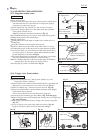
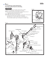
Do not fail two different length Pins to set in place as illustrated in Fig. 22.
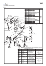
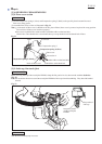
After setting 1R268 instead of Spring pins ø3-20/ ø3-32 temporarily,
push out 1R268 by setting Spring pins ø3-20/ ø3-32 in place. (Fig. 23)
Trigger ass’y can be removed by pushing out two Spring pins ø3-32. (Fig. 22)
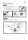
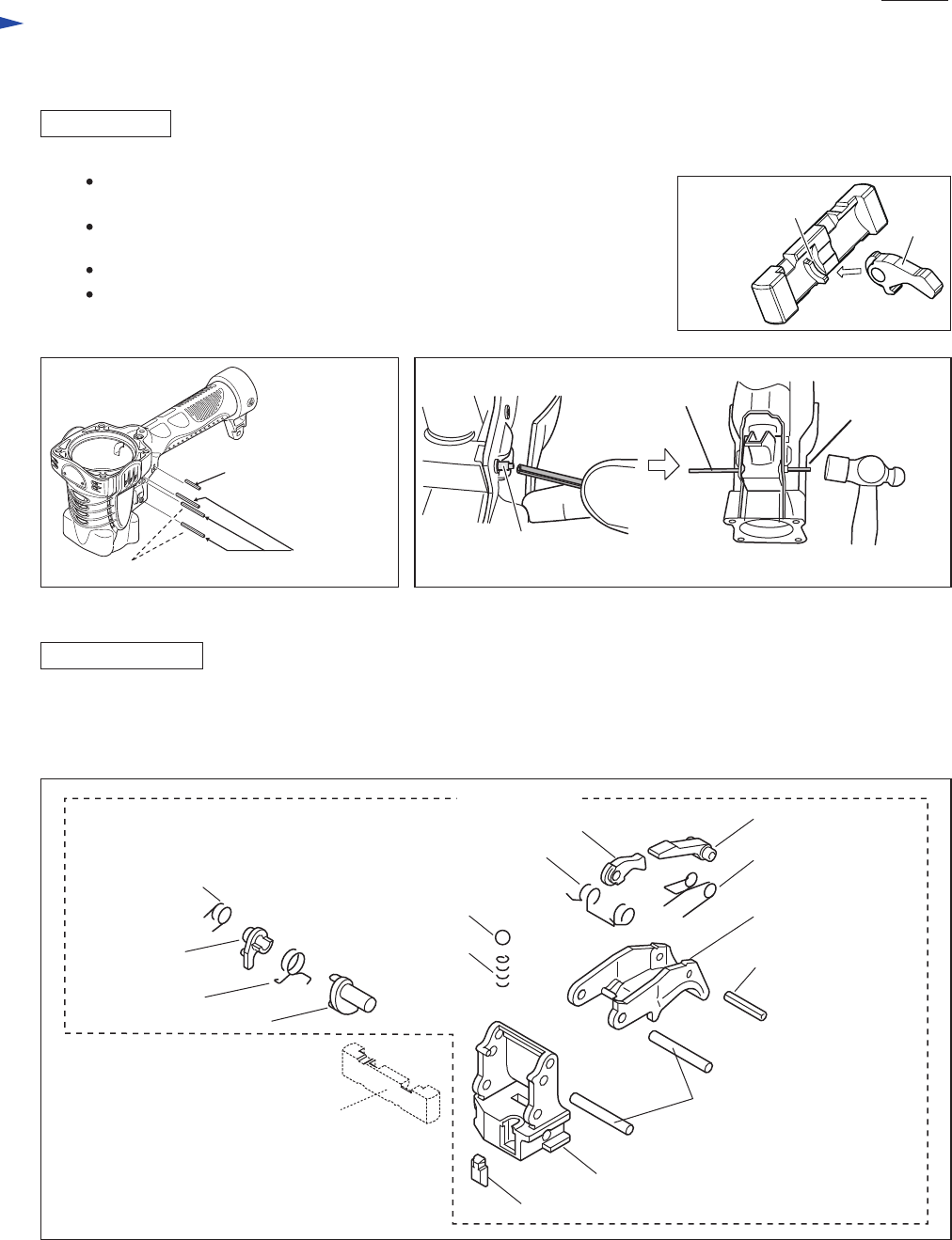
Refer to Fig. 24 for the components as all-in-one package for repair purpose when disassembling Trigger ass’y.
Note: Trigger ass’y does not include Change rod.
Fig. 21
Fig. 23Fig. 22
Fig. 24
DISASSEMBLING
ASSEMBLING
step of 1R268 for
receiving ø3mm Spring pin
1R268
Trip lever
Lever
Torsion spring 4
(Part No. 233503-1)
Steel ball 4
Torsion spring 4
(Part No. 231699-2)
Spring pin 2-12
Spring pin ø3-20
Spring pin
ø3-32 (3pcs.)
(For securing Trigger ass’y)
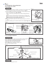
[3]-5. Trigger ass’y
Lever
Center groove
of Change rod
Spring pin
ø3-20/ ø3-32
Torsion spring 5
Stopper plate
Torsion spring 6
Lever
Compression
spring 2
Trigger
Trigger base
Spring cover
Pin 3
(Change rod)
Trigger ass’y