


P 8/ 10
Repair
[3] ASSEMBLING/ DISASSEMBLING
[3]-5. Trigger ass’y (cont.)
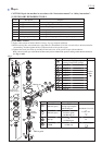
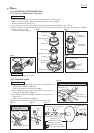
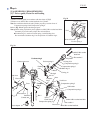
(1) Set Torsion spring 4 (Part No. 233503-1) to the hook of Lever, then pass Pin 3
through Trigger base, Trigger, Torsion spring 4 and Lever. (Fig. 25)
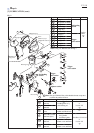
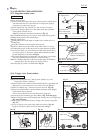
(2) After Assembling Torsion spring 5, Stopper plate, Torsion spring 6 and Lever,
pass Pin 3 through their holes. (Figs. 24 and 26)
Make a round rod by matching the half-arch shapes of Stopper plate and
Lever.
Hook the one leg of Torsion spring 5 with the protrusion of Trigger base.
Hook the other leg of Torsion spring 5 with the protrusion of Stopper plate.
Hook the short leg of Torsion spring 6 with Stopper plate.
Hook the long leg of Torsion spring 6 with Lever.
Note: Do not put Trip lever under Lever. The wrong assembling way will cause
fault.
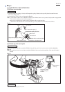
(3) Take the assembling step in accordance with the clause of [3]-4. Trigger valve.
Trigger base
Trigger
Hook of Lever
Pin 3
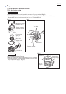
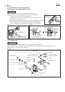
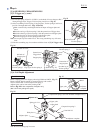
Remove Spring pin 2-14 in Upper yoke using 1R266 and 1R032. (Fig. 27)
Remove Adjust shaft by turning it counterclockwise with careful
not to lose Steel ball 2.3 and Compression spring 2.
Adjuster piece can be removed by turning it 90
°.
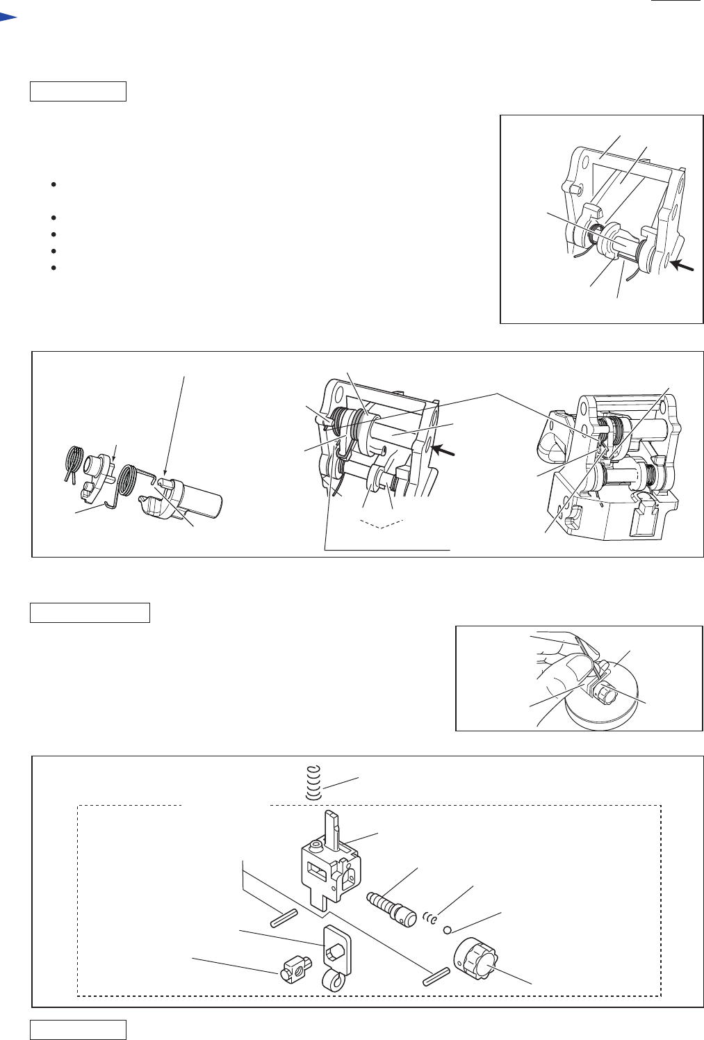
Refer to Fig. 28 for the components of Adjuster ass’y
(that is all-in-one package for repair.)
Take the disassembling step in reverse.
Fig. 25
Fig. 26
Fig. 28
Fig. 27
DISASSEMBLING
ASSEMBLING
ASSEMBLING
1R266
Upper yoke
Spring pin 2-14
Slide plate
Adjuster piece
Compression spring 6 (It is not included in Adjuster ass’y)
1R032
Adjuster
complete
Adjuster complete
Torsion spring 4
short leg of
Torsion spring 6
the other leg of
Torsion spring 5
one leg of
Torsion spring 5
Protrusion of
Stopper plate
Lever Pin 3
Pin 3
Stopper plate
short leg of
Torsion spring 6
half arch of
Stopper plate
half arch of Lever
long leg of Torsion spring 6
(Refer to Fig. 25)
Protrusion of
Trigger base
Lever
[3]-6. Nail Depth Adjustment
Adjuster ass’y
Upper yoke
Adjust shaft
Compression spring 2
Steel ball 2.3