


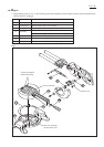
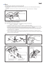
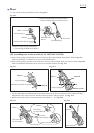

[11] Disassembling positive lock mechanism of turn base
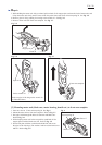
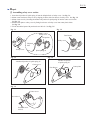
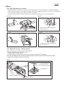
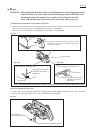
[12] Assembling positive lock mechanism of turn base
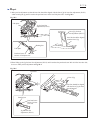
Push compression spring in the direction
designated with arrow (toward grip side).
Fig. 11
Pin 3
Compression
spring 6
Lock pin
Fig. 10-1 Fig. 10-2
Tapping screw
bind CT 4x16
Lock lever
Lock lever plate
Projection of lock lever plate
Grip 32
Grip 32
Apply grease here.
Tapping screw bind CT 4x16
Screw holes
Do the reverse of disassembling procedure with the following attention:
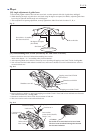
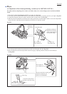
1. The protrusion of lock lever plate has to face the grip side.
2. Apply grease to the threaded portion of the grip.
See Fig. 11.
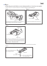
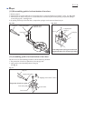
1. Remove grip 32.
2. Separate lock lever plate and lock lever from turn base by removing tapping screw bind CT 4x16. See Fig. 10-1.
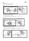
3. Turn lock pin in order to face pin 3 to vertical direction. And remove pin 3 while pushing compression spring 6
toward the grip side. See Fig. 10-2.
4. By pulling off lock pin from turn base, compression spring 6 can be removed from lock pin.
Repair
P 11/ 26
Lock lever plate
Lock lever