


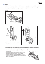
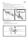
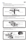
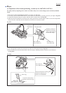

[18] Angle adjustment of guide fence
Screw hole A is smaller
than Screw hole B/C.
Saw blade
90 degrees set square
(No.1R208)
A
B
C
Hex bolt M6x25
Operator's position
Move this side.
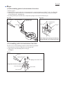
1. Provisionally tighten a M6x25 hex bolt into screw hole A on the operator's left side of guide fence as Fig. 17.
2. While checking the angle of guide rule to saw blade using 90 degrees set square (No.1R208), adjust the guide fence
by moving its right end until the angle sets at 90 degrees
.
3. After completion of squaring adjustment, securely tighten three M6x25 hex bolts in order of C, B, A.
Fig. 17
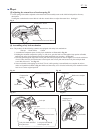
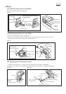
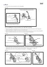
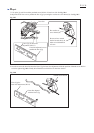
[19] Disassembling laser section (exclusively for LS0714FL/ LS0714L)
1. Remove lock lever from rod 8 before disassembling laser section.
Refer to the chapter < 6 > "Assembling safety lock mechanism".
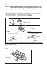
2. After removing thumb screw M5x24, remove top cover by taking off tapping screw bind CT4x20. See Fig. 18-1.
3. Take off laser line label which adheres on blade case, and remove shoulder screw M5 with which laser section is
secured on blade case.
Tapping screw bind CT4x20
Tapping screw bind CT4x20
Thumb screw M5x24
Flat washer 5
Laser line label
Tapping screw bind CT4x20
Shoulder screw M5
Top cover
Fig. 18-1
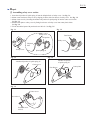
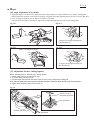
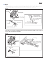
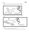
4. Remove lead cover holder by unscrewing tapping screw bind CT4x20. Then, lead coverA and lead cover B can be
removed from blade case. See Fig. 18-2.
5. Disconnect socket unit of laser circuit from connector of lead unit.
6. Then, laser section can be removed from blade case.
Lead cover A
< Caution >
Be careful not to touch the lens for laser beam.
The laser beam irradiated through the smeared
lens becomes indistinct.
Lead cover holder
Lead cover B
Laser section
(Laser circuit, block B,
block C, etc.)
Fig. 18-2
Socket unit of
laser circuit
Connector of
lead unit
Repair
P 14/ 26