


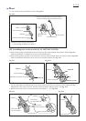
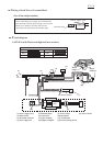
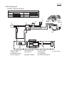
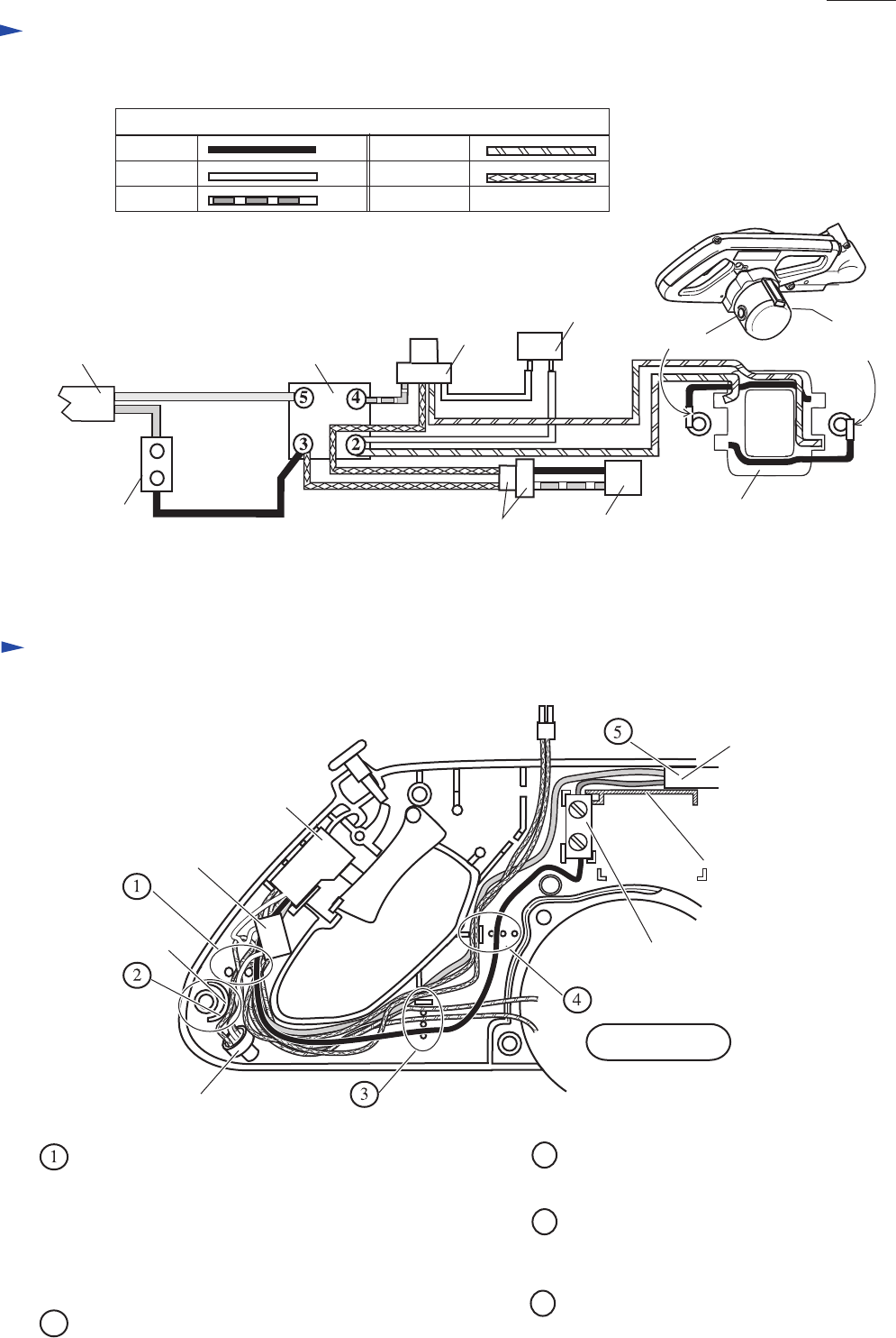
Circuit diagram
Wiring diagram in handle L
Color index of lead wires' sheath
Black
White
Red
Orange
Blue
LS0714F (with Fluorescent light)
LS0714F (with Fluorescent light)
Brush
holder A
Brush
holder B
(1) (2)
(5)
(7)
(8)
(6)
(3)
(4)
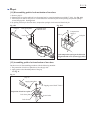
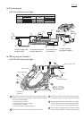
(1) Power supply cord
(2) Main switch
(5) Terminal block
(6) Connectors
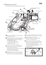
Rib C
Motor housing
Boss
(3) Insulated connector
(4) Noise suppressor
(7) Light assembly
(8) Support complete
Insulated
connector
Noise suppressor
Main switch
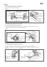
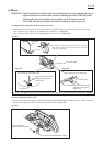
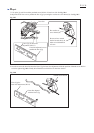
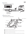
The following lead wires for connecting insulated connector
should be put into lead wire holder so that insulated connector
does not rise from handle L.
* Lead wire (red) to switch
* Lead wire (blue) to light assembly
* Field lead wire (orange)
* Lead wire (white) of noise suppressor
All lead wires have to be put on the right side of boss.
2
5
4
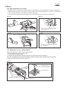
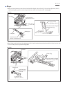
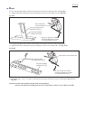
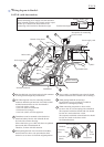
When putting the lead wire into lead wire holders,
the thin lead wires have to be put under the thick
wires so as not to rise from the original position.
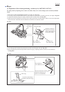
Power supply cord should be put so that its sheath
portion is between Rib C and the wall of housing L.
3
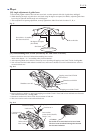
Put field lead wires (orange) into lead wire holder
so that their wires do not sag in the motor housing.
Power supply cord
Terminal block
P 23/ 26