


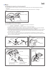
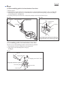
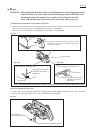
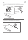
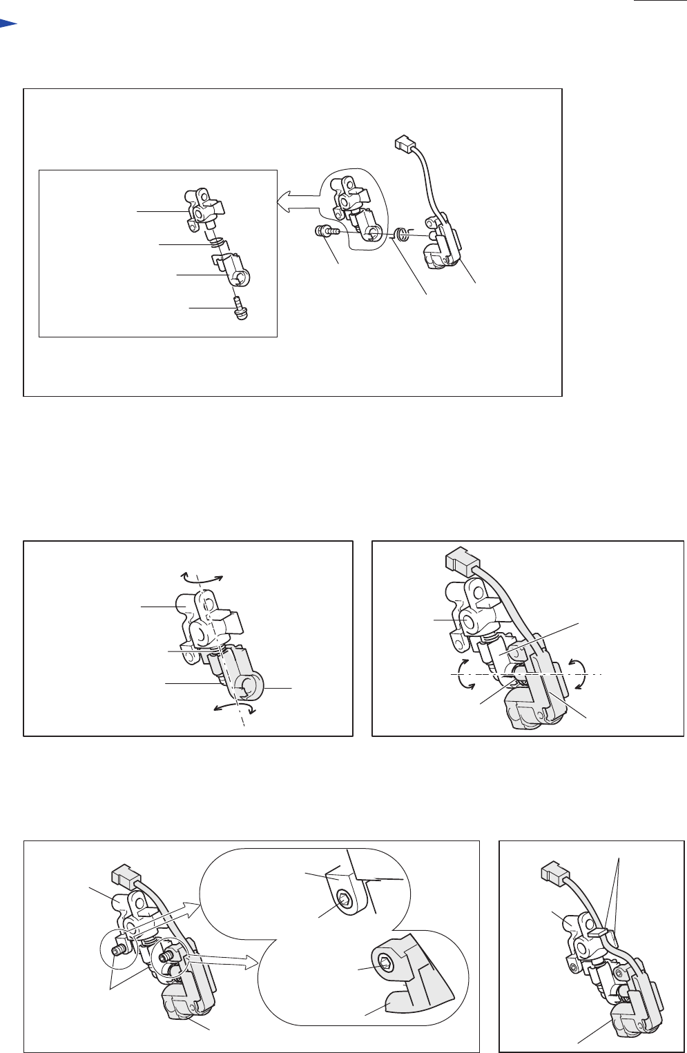
7. Laser section can be disassembled as shown in Fig. 18-3.
Laser circuit
Torsion spring 9
1) Unscrewing pan head screw M3x10 allows
to remove torsion spring 9 and laser circuit.
2) Remove torsion spring 9 and block C
by unscrewing pan head screw M3x10.
Pan head screw
M3x10
Block C
Block B
Torsion spring 9
Pan head screw M3x10
Fig. 18-3
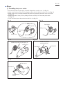
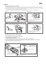
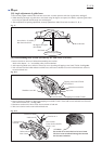
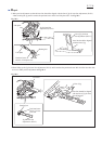
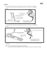
3. For easy adjustment of irradiated angle of laser beam from now on, drive hex socket set screws M4x6 until their
head portions come to the same level with the surfaces of block C and laser circuit. See Fig. 19-3.
4. Hold the lead wires of laser circuit between two ribs of block C. See Fig. 19-4.
Fig. 19-3
Hex socket
set screw M4x6
Hex socket
set screw M4x6
Hex socket
set screw M4x6
Block C
Block C
Laser circuit
Laser circuit
Ribs
Block C
Laser circuit
Fig. 19-4
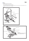
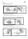
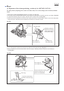
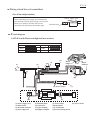
1. Mount torsion spring 9 and block B to block C and secure them with pan head screw M3x10. Refer to Fig. 19-1.
Make sure that block C and block B can move in torsional direction.
2. Mount torsion spring 9 and laser circuit to block B, and secure them with pan head screw M3x10. Refer to Fig. 18-3.
Make sure that block B and laser circuit can move in torsional direction. See Fig. 19-2.
[20] Assembling laser section (exclusively for LS0714FL/ LS0714L)
Block C
Block B
Block B
Torsion spring 9
Block C
Pan head screw M3x10
Torsion spring 9
Laser circuit
Fig. 19-1
Fig. 19-2
Repair
P 15/ 26