


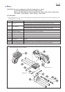
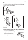
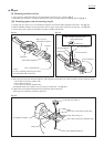
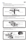
[5]Adjusting the return force of torsion spring 28
Hex socket head set screw M6x16
Return force: Strong
Return force: Weak
Fig. 5
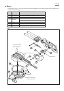
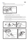
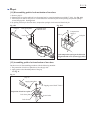
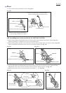
[6] Assembling safety lock mechanism
Note: The products for the following countries are equipped with safety lock mechanism.
* Europe * South Africa * China
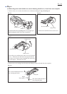
1. Assemble the component parts of safety lock mechanism as illustrated in Fig. 6-1.
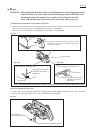
2. Holding the mounted compression spring 7 to lock lever, pass the lock lever through the loop portion of handle,
and bring the safety lock mechanism between handle and blade case complete. See Fig. 6-2.
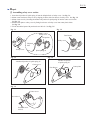
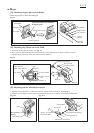
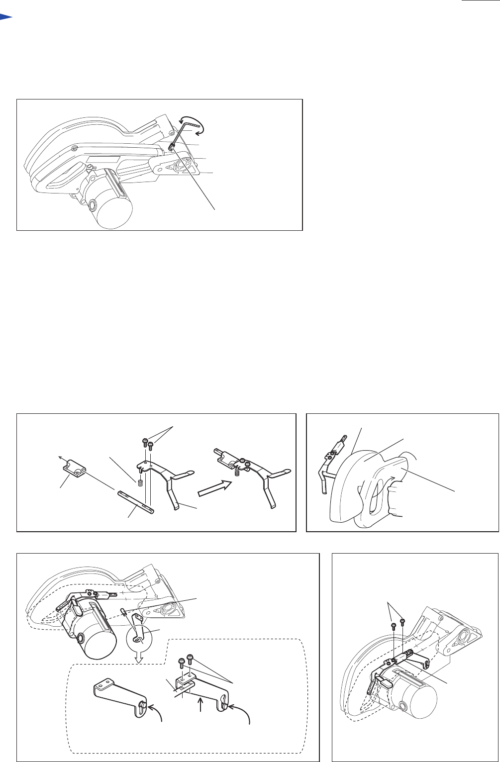
3. Pass lock pin through the large hole of lock plate.And lift up lock plate in order to align its screw holes with those
of rod 8.Then, the lock pin's head comes to the keyhole slot of lock plate.And secure lock plate with pan head
screw M4x10 to rod 8. See Fig. 6-3.
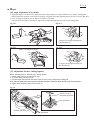
4. Secure rod holder with tapping screw bind CT 4x16, while pressing it toward blade case complete in order to
make rod 8 parallel to handle as Fig. 6-4. Make sure that safety cover is locked with safety lock mechanism when
lock lever is in the original position.
Rod 8
Lock lever
Lock lever
Compression
spring 7
Blade case complete
Handle
Fig. 6-2Fig. 6-1
Lock plate
Rod 8
Lock pin's head unlocked
in keyhole slot
Lock pin's head locked
in the keyhole slot
Lock pin
Fig. 6-4Fig. 6-3
Rod holder
Pan head screw M4x10
Pan head screw
Rod holder
Tapping screw
bind CT 4x16
Repair
P 7 / 26
1. Torsion spring 28 should be adjusted so that motor unit can smoothly return to the initial raised position from any
other place.
Turning hex socket head set screw M6x16 with hex wrench allows to adjust the return force. See Fig. 5.