


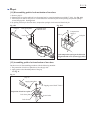
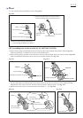
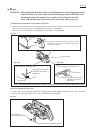

10. Lower the jig again until it reaches the pan head screw M5x16 of link plate side. See Fig. 20-6.
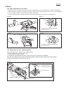
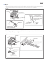
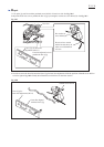
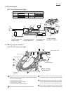
11. Align the laser line with the line of jig by turning hex socket set screw M4x6 (A). See Fig. 20-9.
12. Lift up the jig again until it reaches the pan head screw M5x16 of laser box side. See Fig. 20-7.
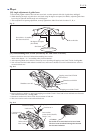
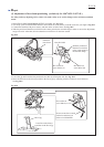
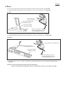
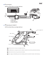
13. Align the laser line with the line of jig by turning hex socket set screw M4x6 (B). See Fig. 20-10.
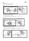
14. Repeat the steps 9, 10, 11, 12 and 13, until the laser line aligns with the line of jig as illustrated in Fig. 20-3 and
Fig. 20-4.
Caution: Laserline label should be pasted again after adjustment.
This prevents dust from invading into the laser circuit and hex socket set screws M4x6 (A and B).
Fig. 20-9
Line of jig for laser line
adjustment (1R315)
Laser line aligning
with the line of jig
Hex socket head
set screw M4x6 (A)
Hex socket set screw M4x6 (B)
Laser line aligning
with the line of jig
Line of jig for laser
line adjustment (1R315)
Fig. 20-10
Be sure to turn hex wrench
clockwise and slowly in order
to avoid backlash of screw.
Be sure to turn hex wrench
clockwise and slowly in order
to avoid backlash of screw.
Repair
P 20/ 26