


DESCRIPTION
OF
OPERATION
(cont'd)
PreSsureReleaseValve: The pressure releasevalve locatedon
the side of the pressure switch, is designed to automatically
releasecompressed airfrom thecompressor head andtheoutlet
tube when the air compressor reaches "cut-out" pressure or is
Outlet Pressure Gauge: The outlet pressure gauge indicates
the air pressure available at the outlet side of the regulator. This
pressure is controlled bythe regulatorand is always lessorequal
to the tank pressure. See "Operating Procedures".
shut
off.
If the air is not released, the motor
will
try
to start, but
will
be unable
to.
The pressure release valve allows the motor to
restart freely.
When
the
motor
stops
running,
air
will
be
heard
escaping from this Valve for a
few
seconds. No air should be
heard leaking when the motor is running, or continuous leaking
after unit reaches cut-out pressure.
Pressure Switch: The pressure switch automatically starts the
motorwhen the air tank pressuredrops below the factory set"cut-
in" pressure.
It
stops the motor when the air tank pressure
reaches the factory set "cut-out" pressure.
Safety Valve: If the pressure switch does not shut
off
the air
compressor at
its
cut-out pressure setting, the safety valve will
protect against high pressure by "popping out" at its factory set
pressure (slightly higherthan the pressure switchcut-outsetting).
Tank Pressure Gauge: The tank pressure gauge indicates the
reserve air pressure in the tank.
Regulator:
The air pressure coming from the air tank
is
con-
trolled bythe regulatorknob.Turn the knobclockwiseto increase
pressure and counterclockwise to decrease pressure. To avoid
minor readjustment after making a change in pressure setting,
always approach the desired pressure from a lower pressure.
When reducing from a higher to a lower setting, first reduce to
some
pressurelessthanthatdesired,
then bring uptothedesired
pressure. Depending on the air requirements of each particular
accessory, the outlet regulated air pressure may have to be
adjusted while you are operating the accessory.
-
INSTALLATION
AND
BREAK-IN
PROCEDURES
-
.. ..
location
of
the Air Compressor
Locate the air compressor in a clean, dry and well ventilated
area. The air filter must be kept clear of obstructions which could
reduce air delivery of the air compressor. The air compressor
should be located at least
12"
away from the wall or other
obstructions that will interfere with the flow
of
air. The air
compressor head and shroud are designed to allow for proper
cooling. If humidity is high, an air filter can be installed on the
air outlet adapter to remove excessive moisture. Follow the
instructions packaged with the air filter for proper installation.
Lubrication and
Oil
This unit needs no lubrication or oiling.
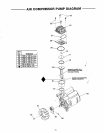
Piping (cont'd)
If
a pipe line is necessary, use pipe that is the same size as the
air tank outlet. Piping that is too small will restrict the flow of air.
If
piping is over
100
feet long, use the next larger size. Bury
underground lines below the frost line and avoid pockets where
condensation can gather and freeze. Apply pres;ure before
underground lines are covered to make sure all pipe joints are
free of leaks.
GROUNDING INSTRUCTION
Extension Cords
To avoid voltage drop, power loss, and overheating of the
motor, use an extra air hose instead of an extension cord.
Low voltage can cause damage to the motor.
RISK
OF
ELECTRICAL SHOCK!
In
the event ota
shortcircuit, grounding reduces the riskof shock
by providing an escape wire for the electric
current. This air compressor must be properly
grounded.
If
an extension cord mustbe used:
use only a 3-wire extension cord that has a 3-blade ground-
ing plug and a 3-slot receptacle that will accept the plug on
the air compressor.
make sure the extension cord is in good condition.
the extension cord should be no longerthan 50feet.
the minimum wire size
is
12 gauge (AWG). (Wire size
increases as gauge number decreases.
10
AWG and
8
AWG
may
also
be used.
DO
NOT
USE
14
AWG or
16
AWG.)
Piping
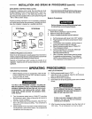
The air compressor is equipped with
a
cord having a grounding
wire with an appropriate grounding plug. The plug must be used
with an outletthat has been installed and grounded in accordance
with
all
local codes and ordinances. The outlet must have the
sameconfiguration astheplug. Seeillustration. DONOTUSEAN
ADAPTER.
Inspect the plug and cord before each use.
Do
not
use if
there are signs
of
damage.
IMPROPER GROUNDING CAN RESULT IN
ELECTRICAL SHOCK.
Plastic or PVC pipe
is
not designed for use with
compressed air. Regardless of its indicated
pressure rating, plastic pipe can burst from air
pressure, Use only metal pipe for air distribution
lines.
Do not modifythe plug that has been provided.
If
it does
not fit the available outlet, the correct outlet should be
installed by a qualified electrician.
continued
IC
6.