


. A complete Parts List is available at www.MillerWelds.com
OM-278 Page 10
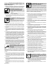
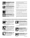
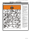
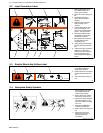
3-7. Symbols And Definitions
Some symbols are found only on CE products.
NOTE
A
Amperes
Amperage/Voltage
Control−Panel
Gas Tungsten Arc
Welding (GTAW)
Shielded Metal Arc
Welding (SMAW)
Temperature Wire Feeder Arc Force (DIG)
Gas Metal Arc
Welding (GMAW)
Output Circuit Breaker Remote
V
Volts
Positive High In-
ductance Weld
Output Terminal
Positive Low In-
ductance Weld
Output Terminal
Negative Weld
Output Terminal
Input
On Off Percent Direct Current
U
0
Rated No Load
Voltage (Average) U
1
Primary Voltage
U
2
Conventional Load
Voltage
Line Connection
I
1
Primary Current
I
2
Rated Welding
Current X
Duty Cycle
Three-Phase
Transformer
Rectifier
IP
Degree Of
Protection
Three-Phase
S
1
KVA
Hz
Hertz
S
Suitable For Areas
Of Increased
Shock Hazard
Protective Earth
(Ground)
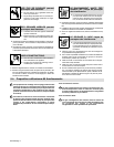
SECTION 4 − INSTALLATION
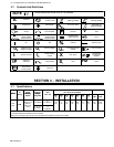
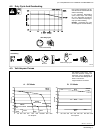
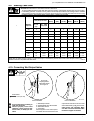
4-1. Specifications
Model
IP
Rated
Welding
Amperage/
Voltage
Max
Amperes Input at Rated Load Output,
50 or 60 Hz, Three-Phase
M
o
d
e
l
IP
Rating
Welding
Output
Voltage
Range DC
Max
OCV−DC
230
V
380
V
400
V
440
V
460
V
520
V
575
V
KVA KW
650
21M
650 A @ 44
Volts DC,
50 − 815 A
In CC Mode
71 (70) VDC
In
CC Mode**
126
3
.
8
*
77
1.
9
*
73
1.
8
*
66
1.
6
*
63
1.
9
*
54
1.1*
50.4
1.4*
50
1.
5
2*
34.8
0
.7
6
*
650
Amp
21M
Volts DC
,
100% Duty
Cycle
10 − 65 V In
CV Mode
40 (66) VDC
In
CV Mode**
3
.
8*
1
.
9*
1
.
8*
1
.
6*
1
.
9*
1
.
1*
1
.
4*
1
.
52*
0
.
76*
*While idling
( ) Indicates specification differences for CE models
**Open-circuit voltage is 26 volts dc if unit is equipped with optional low open-circuit voltage.