


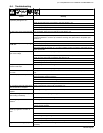
. A complete Parts List is available at www.MillerWelds.com
OM-278 Page 21
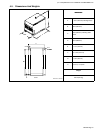
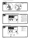
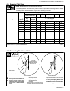
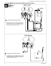
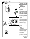
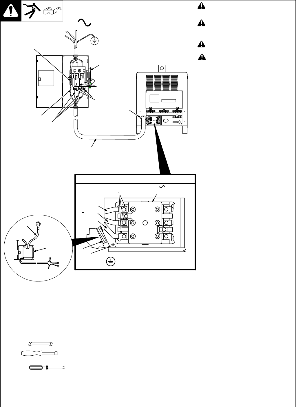
4-18. Connecting Input Power
800 103-C / Ref. 801 116-A
3/8 in
3/8 in
Tools Needed:
! Installation must meet all National
and Local Codes − have only quali-
fied persons make this installation.
! Disconnect and lockout/tagout input
power before connecting input con-
ductors from unit.
! Make input power connections to the
welding power source first.
! Always connect green or green/yel-
low conductor to supply grounding
terminal first, and never to a line ter-
minal.
See rating label on unit and check input volt-
age available at site.
1 Input Power Conductors (Customer
Supplied Cord)
Select size and length of conductors using
Section 4-16. Conductors must comply with
national, state, and local electrical codes. If
applicable, use lugs of proper amperage
capacity and correct hole size.
Welding Power Source Input Power Con-
nections
2 Strain Relief
Route conductors (cord) through strain relief
and tighten screws.
3 Machine Grounding Terminal
4 Green Or Green/Yellow Grounding
Conductor
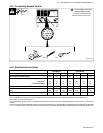
5 Reed Switch (Ground Current Sensor)
(Optional)
Connect green or green/yellow grounding
conductor to welding power source ground-
ing terminal first. If unit is equipped with op-
tional ground current sensor, route ground-
ing conductor through reed switch two times
and connect to grounding terminal.
6 Welding Power Source Line Terminals
7 Input Conductors L1 (U), L2 (V) And
L3 (W)
Connect input conductors L1 (U), L2 (V) and
L3 (W) to welding power source line termi-
nals.
Close and secure access door on welding
power source.
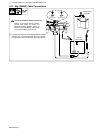
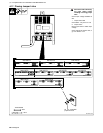
Disconnect Device Input Power Connec-
tions
8 Disconnect Device (switch shown in
OFF position)
9 Disconnect Device (Supply)
Grounding Terminal
Connect green or green/yellow grounding
conductor to disconnect device grounding
terminal first.
10 Disconnect Device Line Terminals
Connect input conductors L1 (U), L2 (V) And
L3 (W) to disconnect device line terminals.
11 Over-Current Protection
Select type and size of over-current protec-
tion using Section 4-16 (fused disconnect
switch shown).
Close and secure door on line disconnect
device. Remove lockout/tagout device, and
place switch in the On position.
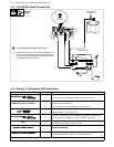
IMPORTANT
GND/
3
PE Earth Ground
Input Contactor
L1 (U)
L2 (V)
L3 (W)
= GND/PE Earth Ground
8
5
4
2
11
6
3
7
4
9
4
10
1
=
7
3