


. A complete Parts List is available at www.MillerWelds.com
OM-278 Page 14
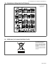
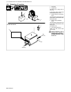
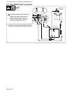
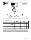
4-6. Tipping
! Be careful when placing or
moving unit over uneven
surfaces.
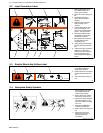
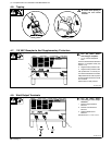
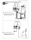
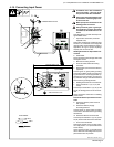
4-7. 115 VAC Receptacle And Supplementary Protectors
3
Ref. 800 166-D
! Turn Off power before
connecting to receptacle.
1 115 V 15 A AC Receptacle
RC9
Power is shared between RC9 and
Remote 14 receptacle RC8 (see
Section 4-15).
2 Supplementary Protector CB1
3 Supplementary Protector CB2
CB1 protects the 115 volts ac por-
tion of RC8 and RC9 from overload.
CB2 protects the 24 volts ac portion
of RC8 and Remote Power On/Off
from overload.
Press button to reset protector.
1
2
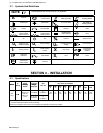
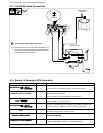
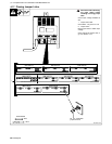
4-8. Weld Output Terminals
Ref. 800 166-D
! Turn Off power before
connecting to weld output
terminals
1 Positive High Inductance
Terminal
2 Positive Low Inductance
Terminal
3 Negative Weld Outout
Terminal
See Sections 4-11, 4-12 or 4-13 .
1
2
3