


. A complete Parts List is available at www.MillerWelds.com
OM-278 Page 22
SECTION 5 − OPERATION
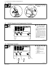
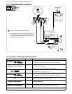
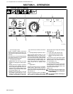
5-1. Controls (Non CE Models)
4
1 2
3
78
56
Ref. 184 939
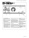
1 Arc Force (Dig) Control
Control increases SMAW short-circuit
amperage which allows the operator to use
a very short arc length without sticking the
electrode.
Set control at 0 for normal welding amperage
and GTAW applications. Turn clockwise to
increase short-circuit amperage.
2 Process Selector Switch
• GMAW Mode: For use with flux Cored
(FCAW) or submerged arc (SAW) applica-
tions.
• SMAW (Hot Start On) Mode: Hot Start is
energized for Stick (SMAW). When Hot
Start is energized, higher short circuit am-
perage aids in arc starting. NOTE: use the
Positive (+) High Inductance weld output
terminal (see Section 4-9).
• SMAW (Hot Start Off) Mode: For use with
TIG (GTAW), scratch start only, or sub-
merged arc (SAW) applications. NOTE:
for GTAW, use the Positive (+) High Induc-
tance weld output terminal (see Section
4-9).
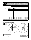
3 Amperage/Voltage Adjustment Control
When Process Selector switch is in the
SMAW/GTAW position, turn control clock-
wise to increase amperage. Read amperage
from outer scale of control. When Process
Selector switch is in the GMAW position, turn
control clockwise to increase voltage. Volt-
meter value changes as control knob is
turned. Control can be adjusted while
welding.
4 Digital Meters
With Process Selector switch in the SMAW/
GTAW position, digital meters will read 0
(zero) with contactor off. Digital meters will
display actual output voltage and amperage
with contactor on.
With Process Selector switch in the GMAW
position, voltmeter displays preset voltage
with contactor off. Voltmeter and ammeter
display actual output voltage and amperage
with contactor on.
5 Power Switch With Indicator Light
6 High Temperature Shutdown Light
7 Remote Amperage/Voltage Control
Switch
For front panel control, place switch in Panel
position. For remote control, place switch in
Remote position, and connect remote de-
vice (see Section 4-15).
8 Output Switch (Contactor)
For front panel control of output, place switch
in Panel position. For remote control of out-
put, place switch in Remote position, and
connect remote device (see
Section 4-15).
! Weld output studs are energized only
when Output switch is in On position,
or while welding.
! Turn Off power before connecting re-
mote device.