


. A complete Parts List is available at www.MillerWelds.com
OM-278 Page 18
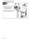
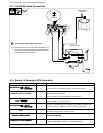
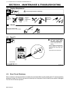
4-13. TIG (GTAW) Cable Connections
++ −
Gas Flowmeter/
Regulator
HIGH
INDUCTANCE
Optional HF Unit
! Turn Off power before making connections.
. For better performance for most GTAW applications, it is
recommended that electrode negative (DCEN) weld output
connections be made to the high Inductance weld output ter-
minal. Make connections as shown.
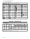
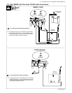
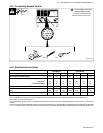
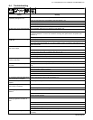
4-14. Remote 14 Receptacle RC8 Information
Socket Information
24 VOLTS AC
A 24 volts ac. Protected by supplementary protector CB2.
24 VOLTS AC
B Contact closure to A completes 24 volts ac contactor control circuit.
C Command reference; 0 to +10 volts dc (CC), +10 volts dc (CV).
REMOTE OUTPUT CONTROL
D Remote control circuit common.
E 0 to +10 volts dc input command signal from remote control.
F Current feedback; 1 volt per 100 amperes.
H Voltage feedback; 1 volt per 10 arc volts.
115 VOLTS AC
I 115 volts, 15 amperes, 60 Hz ac. Protected by supplementary protector CB1.
115 VOLTS AC
J Contact closure to I completes 115 volts ac contactor control circuit.
GND
K
G
Chassis common.
Circuit common for 24 and 115 volts ac circuits.
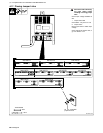
REMOTE POWER ON/OFF
*
To remote On/Off switch
REMOTE POWER ON/OFF
*
T
o
remote
O
n
/Off
sw
i
tc
h
.
REMOTE VOLTAGE SENSING
* Voltage sensing signal from Negative (−) weld output terminal.
REMOTE VOLTAGE SENSING
* Voltage sensing signal from Positive (+) weld output terminal.
* Not Used