


OM-201 540 Page 19
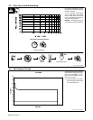
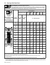
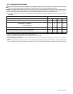
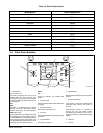
3-12. Electrical Service Guide
Failure to follow these electrical service guide recommendations could create an electric shock or fire hazard. These recommenda-
tions are for a dedicated branch circuit sized for the rated output and duty cycle of the welding power source.
NOTICE − INCORRECT INPUT POWER can damage this welding power source. This welding power source requires a CONTINUOUS supply of
input power at rated frequency(+10%) and voltage (+10%). Phase to ground voltage shall not exceed +10% of rated input voltage. Do not use a genera-
tor with automatic idle device (that idles engine when no load is sensed) to supply input power to this welding power source.
. Actual input voltage should not exceed ± 10% of indicated required input voltage. If actual input voltage is outside of this range, output may not
be available.
60 Hz Three Phase
Input Voltage 230 400 460 575
Input Amperes At Rated Output 89.7 52.0 43.7 21.2
Max Recommended Standard Fuse Rating In Amperes
Circuit Breaker
1
, Time-Delay
2
110 60 50 40
Normal Operating
3
125 80 70 50
Min Input Conductor Size In AWG
4
3 6 8 8
Max Recommended Input Conductor Length In Feet (Meters)
173
(53)
275
(84)
231
(70)
361
(110)
Min Grounding Conductor Size In AWG
4
6 8 8 10
Reference: 2005 National Electrical Code (NEC) (including article 630)
1 Choose a circuit breaker with time-current curves comparable to a Time Delay Fuse.
2 “Time-Delay” fuses are UL class “RK5” .
3 “Normal Operating” (general purpose - no intentional delay) fuses are UL class “K5” (up to and including 60 amp), and UL class “H” ( 65 amp and
above).
4 Conductor data in this section specifies conductor size (excluding flexible cord or cable) between the panelboard and the equipment per NEC Table
310.16. If a flexible cord or cable is used, minimum conductor size may increase. See NEC Table 400.5(A) for flexible cord and cable requirements.