


OM-201 540 Page 25
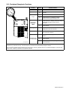
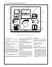
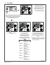
4-3. Front Panel Controls - Continued (See Section 4-2)
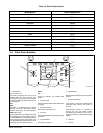
8 Arc Control LED
The LED lights to indicate the Arc Control
button is active. Light goes out when button is
inactive.
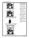
9 Arc Control Push Button
This push button allows fine tuning inductance
for MIG programs, and Arc Control for
programs other than MIG. When the push
button is pressed, the upper display (item 15)
shows INDU for inductance, or ARC for Arc
Control to indicate which parameter is
selected for change. The range of possible
values is 0-99 for inductance, and 0-50 for arc
control. Turn the Adjust knob to change the
parameter value. Press button to deactivate
arc control mode (LED goes out).
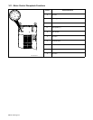
10 Wire Feed/Gas/Contactor LEDs
The Wirefeed LED lights when the wire feeder
is energized. For example, when the front
panel Jog or Retract button is pressed, the
Wirefeed LED lights.
The Gas LED lights when the gas valve is
energized.
The Contactor LED lights when the output
contactor is energized, making the weld
output terminals live.
11 Wire Speed And Amps LED’s
The lit LED indicates whether wire speed or
amps are being displayed.
12 Wire Feed Speed/Amps Display Push
Button
13 Lower Display
Press Wire Feed Speed/Amps Display button
to show weld amperage or wire feed speed in
lower display (the applicable LED under the
lower display lights to indicate which is
shown). When welding, actual value is shown.
If amperage was selected for display, the unit
will show actual welding amperage prior to
and while welding unless the the unit is in
Display Command Values mode. Only wire
speed command will be displayed while
welding if the unit is set in Display Command
Values mode, even if the Wire Feed
Speed/Amps Display button is pressed.
. Displays show actual or command values
as determined by configuration menu
when using a PDA with File Management/
WaveWriter software. Command values
are displayed prior to welding and actual
values are displayed while welding unless
a PDA with File Management software
was used to set the unit in the ”Display
Command Values” mode. In the Display
Command Values mode, command
values are displayed while welding.
. If a PDA with File Management/WaveWriter
software is used to change wire feed units
(IPM, MPM) or display welding information
(command or actual),save the changes and
then turn the power to the unit off and then
on again for the changes to be carried out
by the unit.
14 Volts And Arc Adjust LED’s
The lit LED indicates whether voltage or arc
length is being displayed.
15 Upper Display
The upper display shows different information
depending on the active function of the unit
and the weld process being used. When the
display shows voltage (for a MIG process),
the Volts LED lights. When it shows arc adjust
[for a pulsed and RMD (optional) weld
process], the Arc Adjust LED lights. However,
during any weld process (MIG and pulse), the
unit will display actual arc voltage unless a
PDA with File Management/WaveWriter
software has set the unit in the ”Display
Command Values” mode.
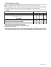
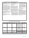
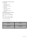
Table 4-1. Welding Wire And Gas Abbreviations*
Wire Description Wire Abbreviation Alloy Type Gas Type Gas Abbreviation
Steel STL E70, E100, E120 100% CO
2
,
90% Argon/10% CO
2
,
85% Argon/15% CO
2
,
75% Argon/25% CO
2
,
95% Argon/5% CO
2
,
95% Argon /5% O
2
,
98% Argon/2% O
2
CO2
C10
C15
C25
C5
OX5
OX2
Stainless Steel SS 308, 309, 312, 316 98% Argon, 2% O
2
(81Ar/18HE/1CO
2
Accu-pulse)
90HE/7-1/2Ar/2-1/2CO
2
MIG/RMD/Accu-pulse)
OX2
Tri Gas
Tri Gas
Cored Tubular Wire MCOR 71, 76, 86R, 409,
439
90% Argon/10% CO
2
C10
439
98% Argon/2% O
2
OX2
Aluminum ALUM 4XXX, 5XXX 100% Argon ARGN
* Not all wire types may be available with your unit.