


OM-201 540 Page 39
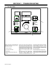
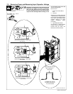
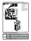
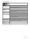
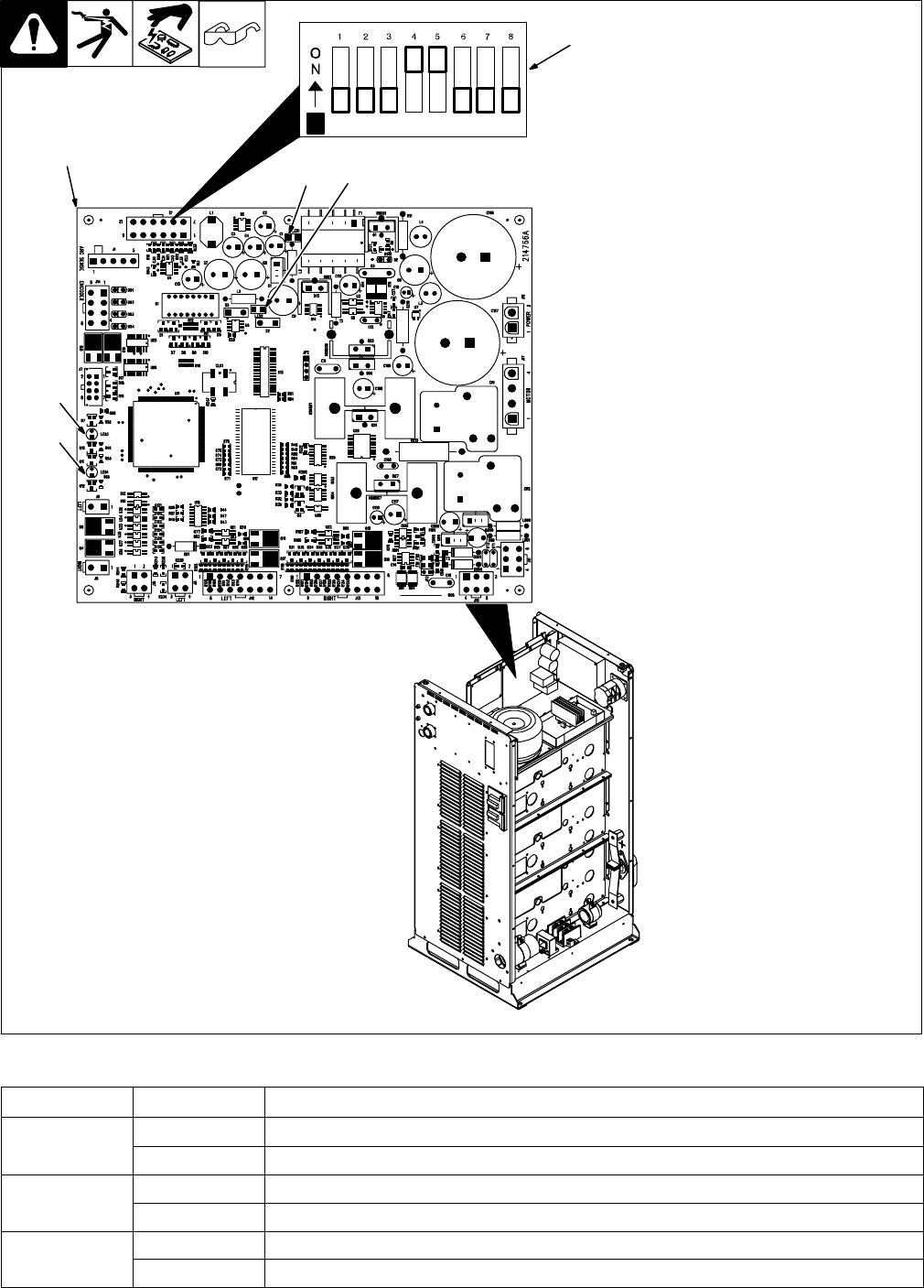
1 Wire Feed Module PC6
Diagnostic LED’s are visible inside
unit, located on PC6 mounted on
the top tray assembly.
Refer to Section 7-7 for information
on diagnostic LED’s.
Reinstall top cover after checking
diagnostic LED’s.
2 Dip Switch S1
Dip switches are used to identify
each circuit board on the internal
network. Dip switch settings are
different for each circuit board. For
proper operation, do not change dip
settings from those shown.
7-6. Wire Feed Module PC6 Diagnostic LED’s And Dip Switch Settings
217 333-B / 803 300-A
2
1
LED1 LED2
LED3
LED4
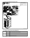
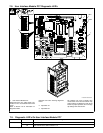
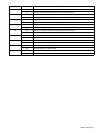
7-7. Diagnostic LED’s On Wire Feed Module PC6
LED Status Diagnosis
1 On Indicates +15 volts dc is present on wire feed module PC6
Off Indicates +15 volts dc is not present on wire feed module PC6
2 On Indicates +5 volts dc is present on wire feed module PC6
Off Indicates +5 volts dc is not present on wire feed module PC6
3,4 On See Network Status Table in Section 7-12
Off See Network Status Table in Section 7-12