


OM-201 540 Page 24
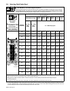
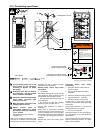
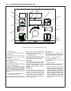
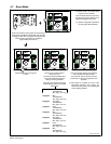
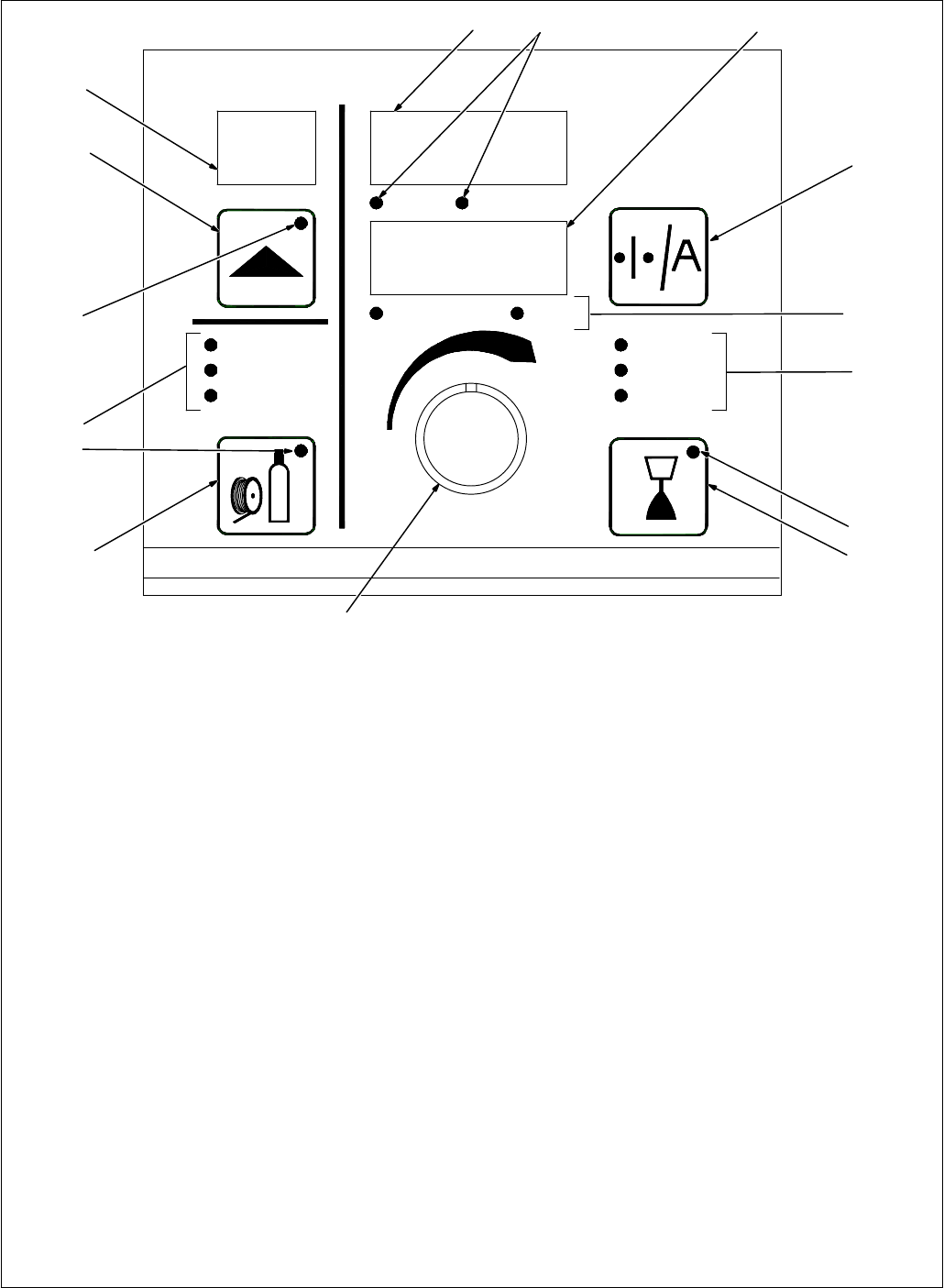
4-2. Front Panel Controls (See Section 4-3)
Program
Process
Wire Type
Gas Type
Adjust
Volts Arc Adjust
Wire Speed Amps
Setup Arc Control
Wirefeed
Gas
Contactor
. When an LED is lit, it means the related function is active.
1 Program Display
Displays the number of the active program.
2 Adjust Knob
Turn the Adjust knob to change program
number, Setup, Arc Control, and weld
parameters.
3 Program Push Button LED
The LED lights when the Program Push
Button is active.
4 Program Push Button
Press push button (LED lights) and turn Adjust
knob to select active program.
The letter C is displayed with the program
number if the program has been changed from
the factory settings using the optional PDA
with File Management/WaveWriter software
(see File Management/WaveWriter Owner’s
Manual).
. The program cannot be changed through
the front panel while welding.
Press and hold button to see program name.
Custom programs are named using optional
PDA with File Management/WaveWriter
software. Program name is shown in upper
and lower displays (items 13 and 15).
5 Setup Mode Indicators
The lit LED indicates which setup mode is
active. Setup mode parameters are shown in
Display Windows (see Items 13 and 15).
Process LED
When this LED is lit, turn the Adjust knob to
select the desired weld process. Choices
include pulse welding (displayed as PULS),
Accu-pulse, MIG welding (MIG), and Accu
Puls/RMD [Regulated Metal Deposition
(optional)].
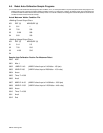
Wire Type LED
When this LED is lit, turn the Adjust knob to
select the desired wire type, wire alloy, and
size. Wire type and size choices vary
according to the selected weld process.
Choices may include steel (displayed as
STL), stainless steel (SS), metal core
(MCOR), aluminum (ALUM). See Table 4-1
for all wire abbreviations.
Gas Type LED
When this LED is lit, turn the Adjust knob to
select the desired weld gas. Gas type choices
vary according to the selected weld process.
See Table 4-1 for all gas abbreviations.
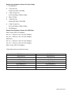
6 Setup Push Button LED
The LED lights to indicate one of the setup
modes is active.
7 Setup Push Button
Press button to select Process, Wire Type,
Wire Diameter, or Gas Type parameters.
. In order for selections to be retained in
memory, the Setup push button must be
pressed six times before any other push
button is pressed: once to select Process,
again to select Wire Type, again to select
Wire Alloy, again to select Wire Size,
again to select Gas Type, and a sixth time
to store selections in memory. The
displays will temporarily show “PROG
LOAD” to indicate the data is being stored
in memory.
198 993
1
2
3
4
5
6
7
8
9
10
11
12
13
1415