


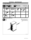
OM-201 540 Page 37
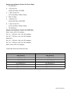
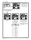
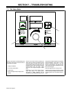
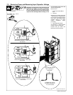
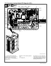
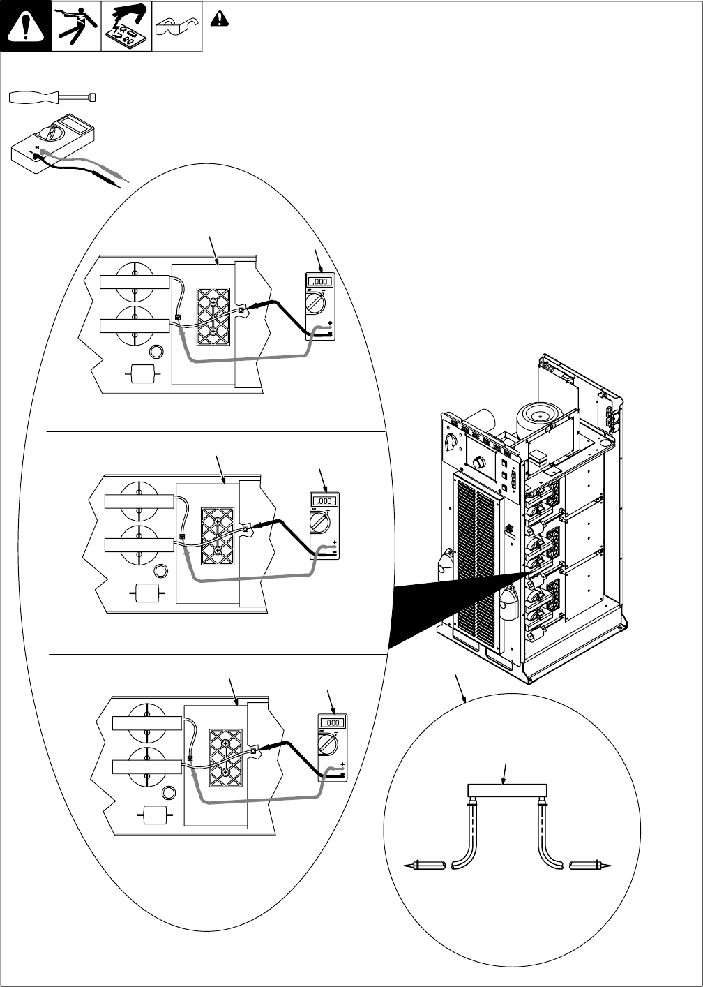
7-3. Removing Cover and Measuring Input Capacitor Voltage
Turn Off welding power source, and
disconnect input power.
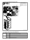
Remove cover
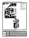
1 Power Interconnect Board
PC2
2 Voltmeter
Measure the dc voltage across the
+ bus terminal and − bus terminal on
PC2 as shown until voltage drops to
near 0 (zero) volts. Measure input
capacitor voltage on all three
inverter assemblies before
proceeding.
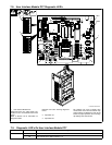
3 Typical Bleeder Resistor
An example of a typical bleeder
resistor is shown on this page.
Proceed with job inside unit.
Reinstall cover when finished.
Tools Needed:
5/16 in
802 301-B / Ref. 803 001-A
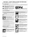
! 900 Volts dc can be present on the capacitor bus and
significant DC voltage can remain on capacitors
after unit is Off. Always check the voltage on both
inverter assemblies as shown to be sure the input
capacitors have discharged before working on unit.
1
2
+ lead to left bus terminal, − lead to right
bus terminal
1
2
1
2
+ lead to left bus terminal, − lead to right
bus terminal
+ lead to left bus terminal, − lead to right
bus terminal
3
Typical Bleeder Resistor
#16 AWG 1000 volts dc
insulation rating, approx
3 in (76 mm) leads
25 to 1000 ohm, 5
watt resistor