


OM-220 389 Page 20
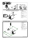
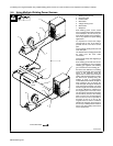
4-11. Connecting Input Power
803 855-A / Ref. 803 766-A / 219 842-A
Tools Needed:
5/16 in
2
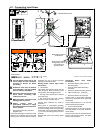
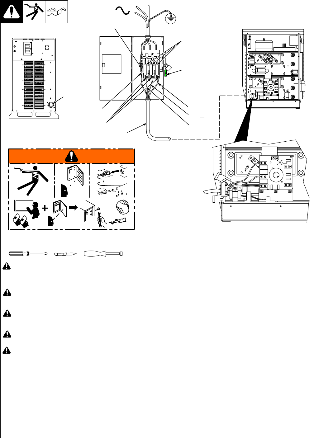
Route ground conductor
through tubing and cur-
rent transducer to
ground terminal.
Route input conductors
to filter board.
219842−A
A
s
l
g
k
d
s
;
lg
k
s
;l
d
f
g
k
s
;d
g
l
k
A
s
l
d
h
f
s
g
k
d
s
;
lg
k
s
;
ld
fg
k
s
;d
g
lk
A
s
l
g
k
d
s
;
lg
k
s
;l
d
f
g
k
s
;d
g
l
k
S
;
ld
k
g
s
ld
g
k
s
d
lk
s
;l
d
fg
k
s
;
d
g
l
k
Kasjf;laksf;lkasdf’l;aksdf;lkasd;flksadflkasd;lk
Kasjf;laksf;lkasdf’l;aksdf;lkasd;flksadflkasd;lk
Kasjf;laksf;lkasdf’l;aksdf;lkasd;flksadflkasd;lk
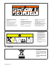
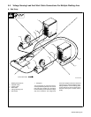
! Turn Off welding power source, and
check voltage on input capacitors
according to Section 9-1 before
proceeding.
! Installation must meet all National
and Local Codes − have only qualified
persons make this installation.
! Disconnect and lockout/tagout input
power before connecting input
conductors from unit.
! Make input power connections to the
welding power source first.
! Always connect green or
green/yellow conductor to supply
grounding terminal first, and never to
a line terminal.
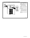
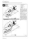
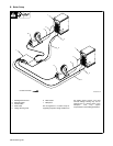
1 Input Power Conductors (Customer
Supplied Cord)
Select size and length of conductors using
Section 4-10. Conductors must comply with
national, state, and local electrical codes. If
applicable, use lugs of proper amperage
capacity and correct hole size.
Welding Power Source Input Power
Connections
2 Strain Relief
Install strain relief of proper size for unit and
input conductors. Route conductors (cord)
through strain relief and tighten screws.
S Use large strain relief for input conductor
size 8 and larger.
S Use small strain relief with reducing
washers for input conductor size 10.
Connect input conductors as shown in
illustration.
Route green or green/yellow grounding
conductor through current transducer and
connect to welding power source grounding
terminal first. Then connect input conductors
L1, L2, and L3 to welding power source line
terminals.
Reinstall side panel onto welding power
source.
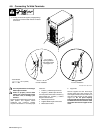
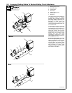
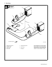
Disconnect Device Input Power
Connections
3 Disconnect Device (switch shown in
the OFF position)
4 Green Or Green/Yellow Grounding
Conductor
5 Disconnect Device Grounding Terminal
6 Input Conductors (L1, L2 And L3)
7 Disconnect Device Line Terminals
Connect green or green/yellow grounding
conductor to disconnect device grounding
terminal first.
Connect input conductors L1, L2, and L3 to
disconnect device line terminals.
8 Over-Current Protection
Select type and size of over-current protec-
tion using Section 4-10 (fused disconnect
switch shown).
Close and secure door on disconnect device.
Remove lockout/tagout device, and place
switch in the On position.
3
3
1
4
5
6
7
8
L1
L2
L3
= GND/PE Earth Ground