


OM-220 389 Page 22
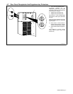
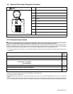
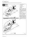
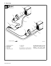
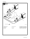
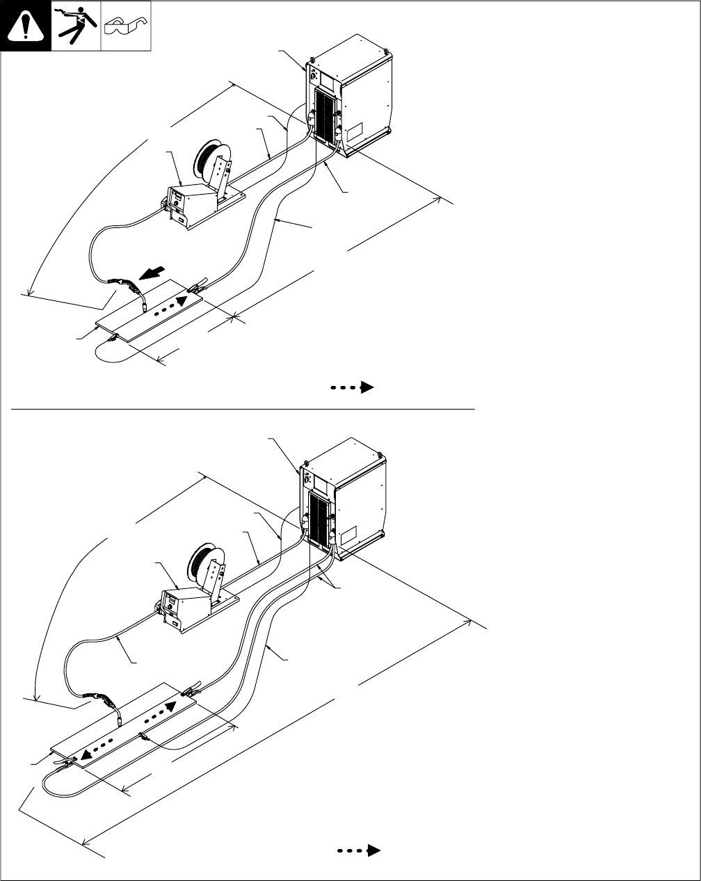
5-2. Welding Circuit
. Minimizing the welding circuit loop can prevent extreme voltage drops that produce poor welding characteristics.
Ref. 804 457-A
1 Welding Power Source
2 Electrode Cable
3 Feeder Cable
4 Work Cable
5 Voltage Sensing Lead
6 Wire Feeder
7 Workpiece
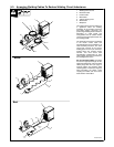
In pulse welding applications using
inverter power sources, cable
resistance can result in less than
satisfactory performance. In most
cases, a welding circuit length of 50 ft
(15 m) or less will provide satisfactory
performance with a standard welding
circuit connection.
The length of a welding circuit is
determined as follows:
Welding Circuit = Electrode Cable
Length (ECL) + Work Cable Length
(WCL) + Workpiece Length (WL)
See Section 5-1 for weld cable size.
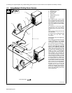
Variations in welding processes and
welding circuit resistance can affect
apparent voltage at the welding arc.
Voltage sensing can improve welding
performance by providing accurate
feedback to the welding power source.
It is important to connect the voltage
sensing lead as near to the weld as
possible, but not in the return current
path.
ECL
WCL
WL
Standard Welding Circuit
ECL
WCL
WL
Large Weld Structure
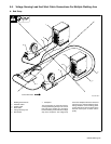
Current Flow Path
Gun
Travel
Current Flow Path
1
3
2
6
2
4
5
7
1
2
3
4
5
6
7