


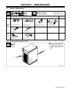
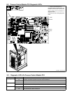
OM-220 389 Page 33
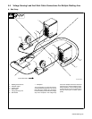
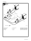
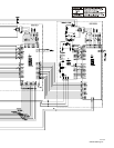
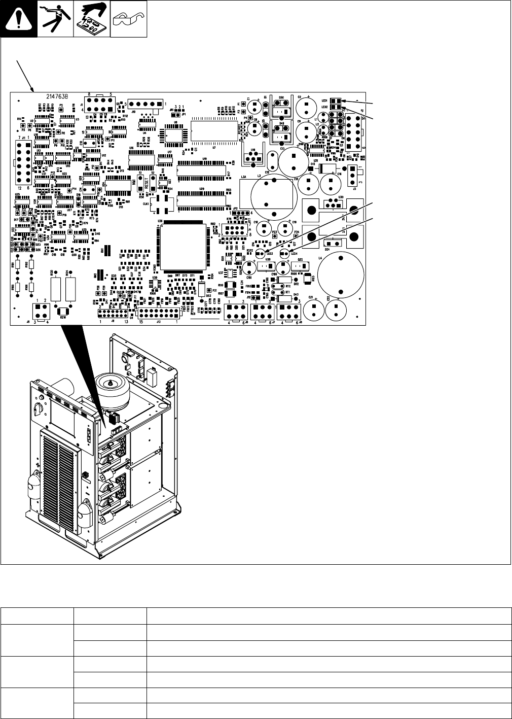
1 Process Control Module PC4
Diagnostic LED’s are visible inside unit,
located on PC4 mounted on the top tray.
Refer to Section 9-3 for information on
diagnostic LED’s.
Reinstall cover after checking diagnostic
LED’s.
216 956-A / Ref. 803 419-B
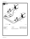
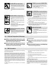
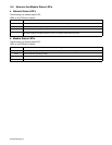
9-2. Process Control Module PC4 Diagnostic LED’s
1
LED2
LED1
LED4
LED3
9-3. Diagnostic LED’s On Process Control Module PC4
LED Status Diagnosis
1 On Indicates −25 volts dc is present on process control module PC4
Off Indicates −25 volts dc is not present on process control module PC4
2 On Indicates +25 volts dc is present on process control module PC4
Off Indicates +25 volts dc is not present on process control module PC4
3,4 On See Network Status Table in Section 9-4
Off See Network Status Table in Section 9-4