


OM-220 389 Page 21
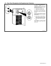
SECTION 5 − RECOMMENDED SETUP PROCEDURES
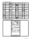
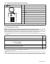
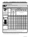
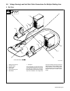
5-1. Selecting Weld Cable Sizes*
! ARC WELDING can cause Electromagnetic Interference.
To reduce possible interference, keep weld cables as short as possible, close together, and down low, such as on the floor.
Locate welding operation 100 meters from any sensitive electronic equipment. Be sure this welding machine is installed
and grounded according to this manual. If interference still occurs, the user must take extra measures such as moving
the welding machine, using shielded cables, using line filters, or shielding the work area.
Weld Cable Size*** and Total Cable (Copper) Length in Weld Circuit
Not Exceeding****
100 ft (30 m) or Less
150 ft
(45 m)
200 ft
(60 m)
250 ft
(70 m)
300 ft
(90 m)
350 ft
(105
m)
400 ft
(120
m)
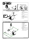
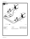
Weld Output
Terminals
! Turn off power before
connecting to weld
output terminals.
! Do not use worn, dam-
aged, undersized, or
poorly spliced cables.
Welding
Amperes**
10 − 60%
Duty
Cycle
60 − 100%
Duty
Cycle
10 − 100% Duty Cycle
100 4 (20) 4 (20) 4 (20) 3 (30) 2 (35) 1 (50) 1/0 (60) 1/0 (60)
150 3 (30) 3 (30) 2 (35) 1 (50) 1/0 (60) 2/0 (70) 3/0 (95) 3/0 (95)
200 3 (30) 2 (35) 1 (50) 1/0 (60) 2/0 (70) 3/0 (95)
4/0
(120)
4/0
(120)
250 2 (35) 1 (50) 1/0 (60) 2/0 (70) 3/0 (95)
4/0
(120)
2 ea. 2/0
(2x70)
2 ea. 2/0
(2x70)
300 1 (50) 1/0 (60) 2/0 (70) 3/0 (95)
4/0
(120)
2 ea. 2/0
(2x70)
2 ea. 3/0
(2x95)
2 ea. 3/0
(2x95)
350 1/0 (60) 2/0 (70) 3/0 (95)
4/0
(120)
2 ea. 2/0
(2x70)
2 ea. 3/0
(2x95)
2 ea. 3/0
(2x95)
2 ea. 4/0
(2x120)
400 1/0 (60) 2/0 (70) 3/0 (95)
4/0
(120)
2 ea. 2/0
(2x70)
2 ea. 3/0
(2x95)
2 ea. 4/0
(2x120)
2 ea. 4/0
(2x120)
500 2/0 (70) 3/0 (95) 4/0 (120)
2 ea. 2/0
(2x70)
2 ea. 3/0
(2x95)
2 ea. 4/0
(2x120)
3 ea. 3/0
(3x95)
3 ea. 3/0
(3x95)
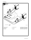
Positive
)
Negative
600 3/0 (95) 4/0 (120)
2 ea. 2/0
(2x70)
2 ea. 3/0
(2x95)
2 ea. 4/0
(2x120)
3 ea. 3/0
(3x95)
3 ea. 4/0
(3x120)
3 ea. 4/0
(3x120)
Positive
)
Negative
*
Ref. 803 418-B
700 4/0 (120)
2 ea. 2/0
(2x70)
2 ea. 3/0
(2x95)
2 ea. 4/0
(2x120)
3 ea. 3/0
(3x95)
3 ea. 4/0
(3x120)
3 ea. 4/0
(3x120)
4 ea. 4/0
(4x120)
800 4/0 (120)
2 ea. 2/0
(2x70)
2 ea. 3/0
(2x95)
2 ea. 4/0
(2x120)
3 ea. 4/0
(3x120)
3 ea. 4/0
(3x120)
4 ea. 4/0
(4x120)
4 ea. 4/0
(4x120)
* This chart is a general guideline and may not suit all applications. If cable overheating occurs, use next size larger cable.
**Cable should be sized for Peak Amperage (Apk) for pulse welding applications.
***Weld cable size (AWG) is based on either a 4 volts or less drop or a current density of at least 300 circular mils per ampere.
( ) = mm
2
for metric use
****For distances longer than those shown in this guide, call a factory applications representative at 920-735-4505. S-0007-E
. In pulse welding applications using inverter power sources, peak currents can result in extreme voltage drops producing poor welding
characteristics with undersized cables. A recommendation for weld cable size is a minimum of 2/0 for 300 ampere welding power sources and
4/0 for 450 ampere welding power sources when total cable length is less than 100 ft (30m).