


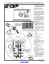

OM-495 Page 39
Return To Table Of Contents
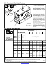
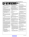
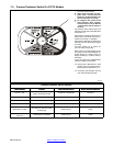
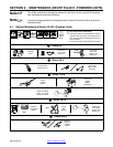
7-2. Description Of Front Panel Controls For CC/CV Models (See Section 7-1)
Engine Starting Controls
1 Magnetic Shutdown Switch
Use switch during start-up to bypass engine
shutdown system. System stops engine if oil
pressure is too low or engine temperature is
too high.
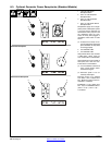
2 Starting Aid Switch (Optional)
Use switch to energize starting aid for cold
weather starting.
Deutz F4L2011-powered units use a glow
plug starting aid. Push switch up for 60 sec-
onds to operate the glow plug before cranking
engine (see starting instructions following).
Deutz F3L912-powered units use an ether
starting aid system. Push switch up and re-
lease while cranking engine to release ether
(see starting instructions following).
3 Engine Control Switch
Use switch to start engine, select engine
speed (if unit has auto idle option), and stop
engine.
In Run position, engine runs at weld/power
speed. In Run/Idle position (optional), engine
runs at idle speed at no load and weld speed
with load applied.
To Start:
. If engine does not start, let engine come
to a complete stop before attempting re-
start.
Above 325 F (05 C): turn Engine Control
switch to Start while pressing Shutdown
switch. Release Engine Control switch when
engine starts. Continue holding Shutdown
switch until engine indicator lights go out.
Below 325 F (05 C) using optional starting
aid switch:
Deutz F4L2011-powered units − Turn Engine
Control switch to Run/Idle position. Push
Starting Aid switch up for 60 seconds. While
still holding Starting Aid switch, press Mag-
netic Shutdown switch and turn Engine Con-
trol switch to Start. Release Engine Control
switch and Starting Aid switch when engine
starts. Continue holding Shutdown switch un-
til engine indicator lights go out.
Deutz F3L912-powered units − Press Mag-
netic Shutdown switch and turn Engine Con-
trol switch to Start. While cranking engine,
push Starting Aid switch up and release. Re-
lease Engine Control switch when engine
starts. Continue holding Shutdown switch un-
til engine indicator lights go out.
To Stop: turn Engine Control switch to Off
position.
Engine Indicator Lights
4 Battery Charging Light
Light goes on if engine alternator is not charg-
ing battery. Engine continues to run.
Y Stop engine and fix trouble if Battery
Charging light goes on.
5 Engine Temperature Light
Light goes on and engine stops if engine oil
temperature is above 266 ° F (130° C).
Y Stop engine and fix trouble if Engine
Temperature light goes on.
6 Engine Oil Pressure Light
Light goes on and engine stops if oil pressure
is below 22 psi (150 kPa). Light goes on mo-
mentarily during start-up but goes out when
engine reaches normal oil pressure.
Y Stop engine and fix trouble if Engine
Oil Pressure light stays on after start-
up.
7 Fuel Light
Fuel light is not active on this model.
8 Engine Hour Meter
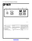
Engine Gauges
. To read gauges and engine indicator
lights with engine off, turn Engine Control
switch to Run/Idle and press Magnetic
Shutdown switch (see Section 11-1).
9 Fuel Gauge
Use gauge to check fuel level.
To check fuel level when engine is not run-
ning, turn Engine Control switch to Run/Idle
position and press Magnetic Shutdown
switch.
10 Battery Voltmeter (Optional)
Use gauge to check battery voltage and moni-
tor the engine charging system. The meter
should read about 14 volts dc when the en-
gine is running, and about 12 volts dc when
the engine is stopped.
11 Engine Temperature Gauge (Optional)
Normal temperature is 212 - 239° F (100 -
115° C). If equipped with gauge option, engine
stops if temperature exceeds 270° F (132° C).
12 Engine Oil Pressure Gauge (Optional)
Normal pressure is 30 − 60 psi (206 − 414
kPa). If equipped with gauge option, engine
stops if pressure is below 20 psi (138 kPa).
Weld Controls
13 Process/Contactor Switch
See Section 7-3 for Process/Contactor
switch information.
14 Ampere Range Switch
Y Do not switch under load.
Use switch to select weld amperage range.
Use the lowest four ranges for Stick and TIG
welding. Read the upper set of numbers at
each range for Stick welding and the lower set
at each range for TIG welding.
Use the highest range for MIG welding and for
cutting and gouging (CAC-A).
For most welding applications, use lowest
amperage range possible to help prevent arc
outages.
15 Voltage/Amperage Adjust Control
With Process/Contactor switch in any Stick or
TIG setting, use control to adjust amperage
within range selected by Ampere Range
switch. With Process/Contactor switch in any
MIG position, use control to adjust voltage.
With Voltage/Amperage Adjust Switch in Re-
mote position, control limits the remote am-
perage in TIG mode, but has no effect in Stick
and MIG modes.
Weld output would be about 223 A DC with
controls set as shown (50% of 125 to 320 A).
. The numbers around the control are for
reference only and do not represent an
actual percentage value.
16 Voltage/Amperage Adjust Switch And
Remote 14 Receptacle
Use switch to select front panel or remote
voltage/amperage control. For remote con-
trol, place switch in Remote position and con-
nect remote control to Remote 14 receptacle
RC14 (see Sections 5-13 and 7-4).
17 Polarity Switch (Optional)
Y Do not switch under load.
Use switch to change weld output. Select ei-
ther DC Electrode Positive (DCEP) or DC
Electrode Negative (DCEN).
Weld Meters
18 DC Voltmeter (Optional)
Voltmeter displays voltage at the weld output
terminals, but not necessarily the welding arc
due to resistance of cable and connections.
19 DC Ammeter (Optional)
Ammeter displays amperage output of the
unit.