


OM-611 Page 9
Return To Table Of Contents
SECTION 3 − INSTALLATION
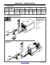
3-1. Specifications
Welding
Circuit Rat-
Input Powe
r
Cord With
Type Of Input Power Dimensions Weight
Circuit Rat-
ing
Cord With
Plug
115 Volts 230 Volts Height Width Length 115 Volts 230 Volts
250 Amperes
At 60% Duty
Cycle
10 ft (3 m)
115 Volts AC
Single-Phase
50/60/100 Hz,
1.5 Amperes
230 Volts AC
Single-Phase
50/60 Hz,
0.75 Amperes
15 in
(381 mm)
9-1/4 in
(235 mm)
16 in
(406 mm)
Net:
34 lb (15 kg)
Ship:
37 lb (17 kg)
Net:
36 lb (16 kg);
Ship:
39 lb (18 kg)
Ref. 159 606-B / 159 607-A
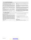
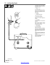
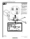
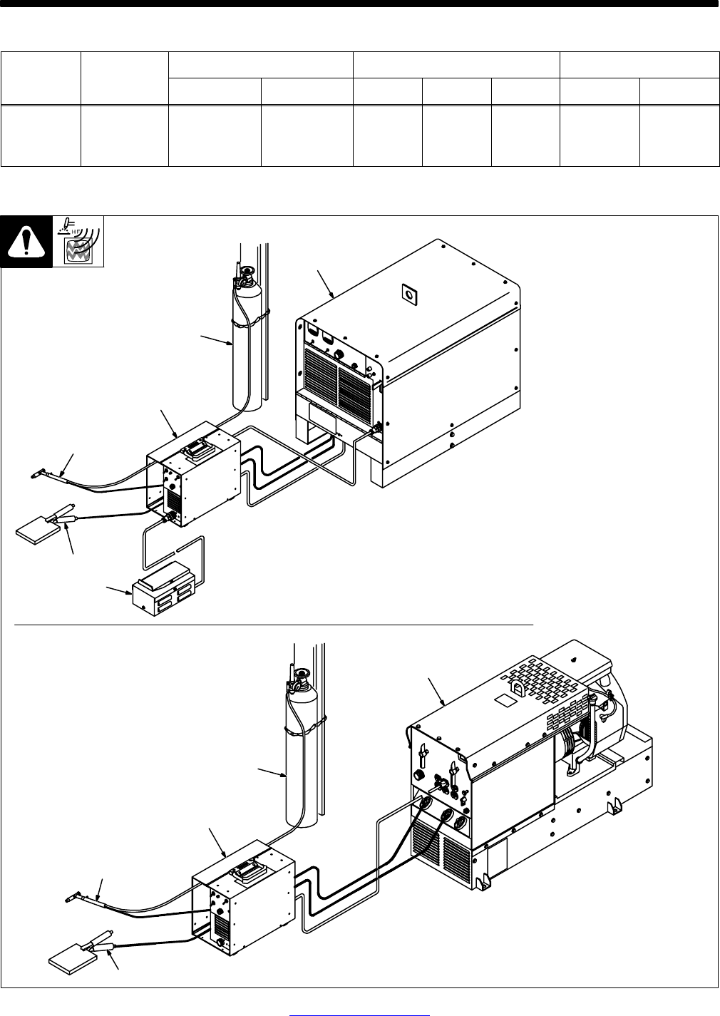
Y Read and follow entire Sec-
tion 8 for proper location and
installation requirements for
high-frequency equipment
before installing unit.
1 Welding Power Source
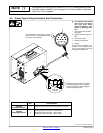
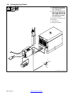
2 Gas Cylinder
3 HF Unit
4 Torch
5 Work Clamp
6 Foot Control
7 Welding Generator
1
2
3
4
5
6
2
3
4
5
7
3-2. Typical Process Connections
Typical Welding Power
Source Installation
Typical Welding
Generator Installation