


OM-611 Page 23
Return To Table Of Contents
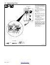
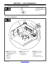
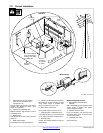
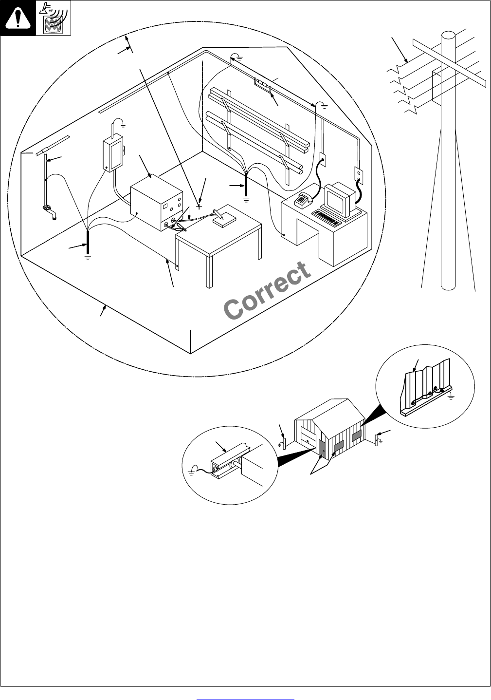
7-3. Correct Installation
1 High-Frequency Source (welding
power source with built-in HF or
separate HF unit)
Ground metal machine case, work output
terminal, line disconnect device, input
supply, and worktable.
2 Center Point of Welding Zone
Midpoint between high-frequency source
and welding torch.
3 Welding Zone
A circle 50 ft (15 m) from center point in all
directions.
4 Weld Output Cables
Keep cables short and close together.
5 Conduit Joint Bonding and Grounding
Electrically join (bond) all conduit sections
using copper straps or braided wire.
Ground conduit every 50 ft (15 m).
6 Water Pipes and Fixtures
Ground water pipes every 50 ft (15 m).
7 External Power or Telephone Lines
Locate high-frequency source at least 50 ft
(15 m) away from power and phone lines.
8 Grounding Rod
Consult the National Electrical Code for
specifications.
Metal Building Requirements
9 Metal Building Panel Bonding
Methods
Bolt or weld building panels together, install
copper straps or braided wire across
seams, and ground frame.
10 Windows and Doorways
Cover all windows and doorways with
grounded copper screen of not more than
1/4 in (6.4 mm) mesh.
11 Overhead Door Track
Ground the track.
Ref. S-0695 / Ref. S-0695
1
2
3
50 ft
(15 m)
Weld Zone
4
7
50 ft
(15 m)
8
5
8
6
Ground
workpiece
if required
by codes.
Ground all metal ob-
jects and all wiring in
welding zone using
#12 AWG wire.
Nonmetal
Building
9
11
10
Metal Building
8
8