


OM-611 Page 11
Return To Table Of Contents
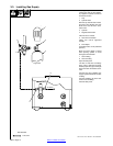
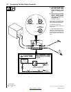
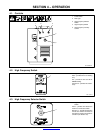
The supplied cord with plugs is for use with CC or CC/CV welding power sources
having the proper, matching 14-pin receptacle. Do not use cordset on machines
without the 14-pin receptacle.
NOTE
159 645-A / Ref. S-0004-A / S-0283-A
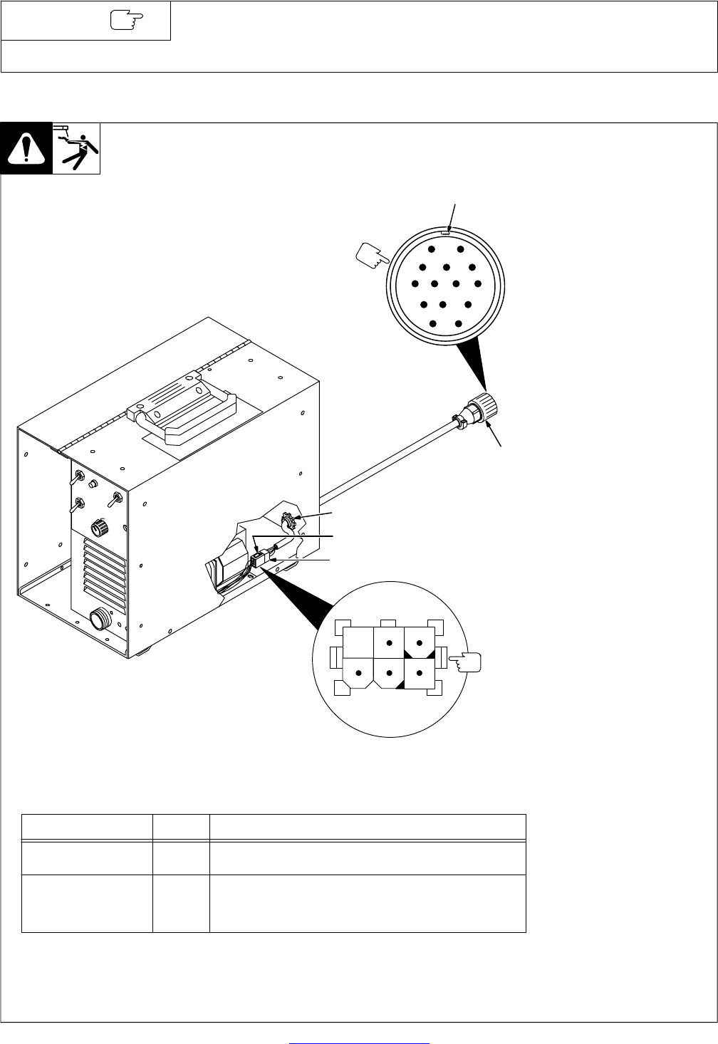
Y Turn Off HF Unit and welding
power source, and discon-
nect input power before
making connections. Stop
engine on welding genera-
tors.
1 Six-Pin Power Source Block
Plug PLG2
2 Supplied Six-Pin Receptacle
RC2
3 Strain Relief Clamp
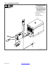
4 Remote 14 Plug PLG4
5 Keyway
To Connect PLG4 to Remote 14 re-
ceptacle on the welding power
source, align keyway, insert plug
and tighten threaded collar.
Connect Remote 14 Plug PLG4 if remote
contactor and/or remote amperage control
from the HF unit are desired.
AJ
B
K
I
C
L
NH
D
M
G
E
F
5
4
3
2
1
21
654
3
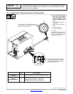
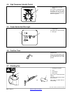
The following pin information is included
in case the supplied cord is not suitable,
and it is necessary to wire a receptacle
to interface with plug PLG2.
Front View
Of PLG2
Pin* Pin Informaton
Remote
Contactor Control
Remote
Amperage Control
1, 2
*The remaining pin is not used.
3
4
5
Provides contact closure for Output (Contactor) operation.
Amperage control connection − maximum side.
Amperage control connection − wiper contact.
Amperage control connection − minimum side.
3-4. Power Source Plug Information And Connections