


OM-611 Page 10
Return To Table Of Contents
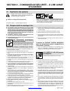
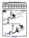
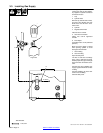
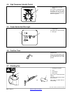
Obtain gas cylinder and chain to
running gear, wall, or other station-
ary support so cylinder cannot fall
and break off valve.
1 Cap
2 Cylinder Valve
Remove cap, stand to side of valve,
and open valve slightly. Gas flow
blows dust and dirt from valve.
Close valve.
3 Cylinder
4 Regulator/Flowmeter
Install so face is vertical.
5 Gas Hose Connection
Fitting has 5/8-18 right-hand
threads.
6 Flow Adjust
Typical flow rate is 15 cfh (cubic feet
per hour).
Make sure flow adjust is closed
when opening cylinder to avoid
damage to the flowmeter.
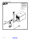
7 Gas In Fitting
8 Gas Out Fitting
Open left side panel.
The Gas In and Gas Out fittings
have 5/8-18 right-hand threads.
Obtain proper size, type, and length
hose and make connections as fol-
lows:
Connect hose from shielding gas
supply regulator/flowmeter to Gas
In fitting.
Connect shielding gas hose from
torch to Gas Out fitting.
Close left side panel.
ssb3.3* 5/94 − Ref. 158 697-A / Ref. 098 956-B
Tools Needed:
1-1/8, 5/8 in
1
2
3
4
5
6
7
8
To Torch
Argon Gas
IN-GAS-OUT
3-3. Installing Gas Supply