


OM-2233 Page 16
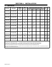
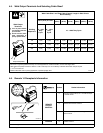
4-5. Weld Output Terminals And Selecting Cable Sizes*
Weld Cable Size** and Total Cable (Copper) Length in Weld Circuit
Not Exceeding
100 ft (30 m) Or Less
150 ft
(45 m)
200 ft
(60 m)
250 ft
(70 m)
300 ft
(90 m)
350 ft
(105 m)
400 ft
(120 m)
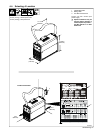
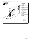
Weld Output
Terminals
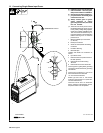
Y Turn off power before
connecting to weld out-
put terminals.
Y Do not use worn, dam-
aged, undersized, or
poorly spliced cables.
Welding
Amperes***
10 − 60%
Duty
Cycle
60 − 100%
Duty
Cycle
10 − 100% Duty Cycle
100 4 (20) 4 (20) 4 (20) 3 (30) 2 (35) 1 (50) 1/0 (60) 1/0 (60)
150 3 (30) 3 (30) 2 (35) 1 (50) 1/0 (60) 2/0 (70) 3/0 (95 3/0 (95)
200 3 (30) 2 (35) 1 (50) 1/0 (60) 2/0 (70) 3/0 (95) 4/0 (120) 4/0 (120)
+
Output Receptacles
−
+
* This chart is a general guideline and may not suit all applications. If cable overheats, use next size larger cable.
**Weld cable size (AWG) is based on either a 4 volts or less drop or a current density of at least 300 circular mils per ampere.
( ) = mm
2
for metric use
***Select weld cable size for pulsing application at peak amperage value. S-0007-E−
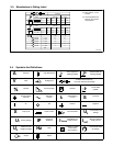
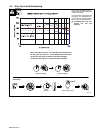
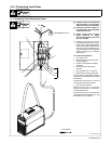
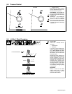
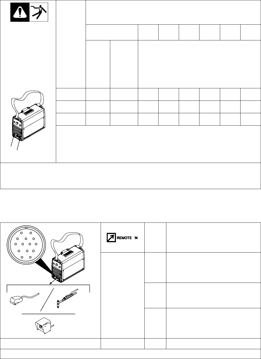
4-6. Remote 14 Receptacle Information
AJ
B
K
I
C
L
NH
D
M
G
Socket* Socket Information
D
M
G
E
F
C Output to remote control; 0 to +10 volts dc output
to remote control.
REMOTE
OUTPUT
CONTROL
D Remote control circuit common.
ST-802 541
E 0 to +10 volts dc input command signal from
remote control.
CHASSIS
K Chassis common.
*The remaining sockets are not used.