


OM-2233 Page 18
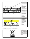
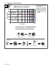
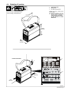
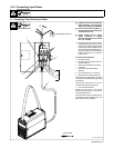
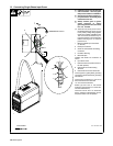
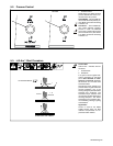
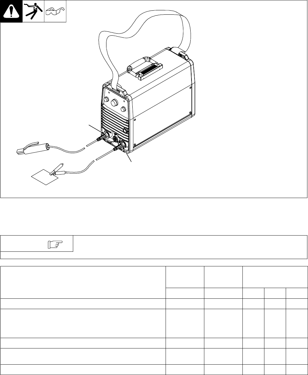
4-8. Stick DCEP (Direct Current Electrode Positive) Connections
Ref. 802 888-A
Y Turn off power before mak-
ing connections.
1 Negative (−) Weld Output
Terminal
Connect work lead to negative weld
output terminal.
2 Positive (+) Weld Output
Terminal
Connect electrode holder to posi-
tive weld output terminal.
1
2
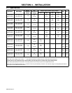
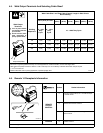
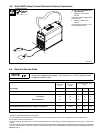
4-9. Electrical Service Guide
Actual input voltage cannot exceed - 10% of minimum or +10% of maximum input
voltages indicated in table.
NOTE
Single-Phase,
100% Duty
Cycle
Single-Phase,
60% Duty
Cycle
Three-Phase, 60% Duty
Cycle
Input Voltage
115 230 230 400 460
Input Amperes At Rated Output 25 22 13.1 7.4 6.4
Max Recommended Standard Fuse Rating In Amperes
1
Time Delay
2
25 25 15 8 8
Normal Operating
3
35 30 20 10 10
Min Input Conductor Size In AWG
4
10 12 14 14 14
Max Recommended Input Conductor Length In Feet (Meters) 57 (17) 79 (24)
102
(31)
308
(94)
407
(124)
Min Grounding Conductor Size In AWG
4
10 12 14 14 14
Reference: 2005 National Electrical Code (NEC)
1 If a circuit breaker is used in place of a fuse, choose a circuit breaker with time-current curves comparable to the recommended fuse.
2 “Time-Delay” fuses are UL class “RK5” .
3 “Normal Operating” (general purpose - no intentional delay) fuses are UL class “K5” (up to and including 60 amp), and UL class “H” ( 65 amp and
above).
4 Conductor data in this section specifies conductor size (excluding flexible cord or cable) between the panelboard and the equipment per NEC Table
310.16. If a flexible cord or cable is used, minimum conductor size may increase. See NEC Table 400.5(A) for flexible cord and cable requirements.