


OM-2233 Page 19
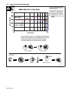
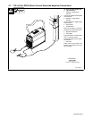
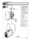
4-10. Connecting Input Power
2/04 - Ref. 802 136-A
Y Installation must meet all National
and Local Codes − have only quali-
fied persons make this installation.
Y Disconnect and lockout/tagout in-
put power before connecting input
conductors from unit.
Y Always connect green or green/
yellow conductor to supply
grounding terminal first, and never
to a line terminal.
. The Auto-Line circuitry in this unit au-
tomatically adapts the power source
to the primary voltage being applied.
Check input voltage available at site.
This unit can be connected to any in-
put power between 120 and 460 VAC
without removing cover to relink the
power source.
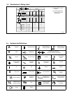
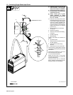
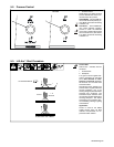
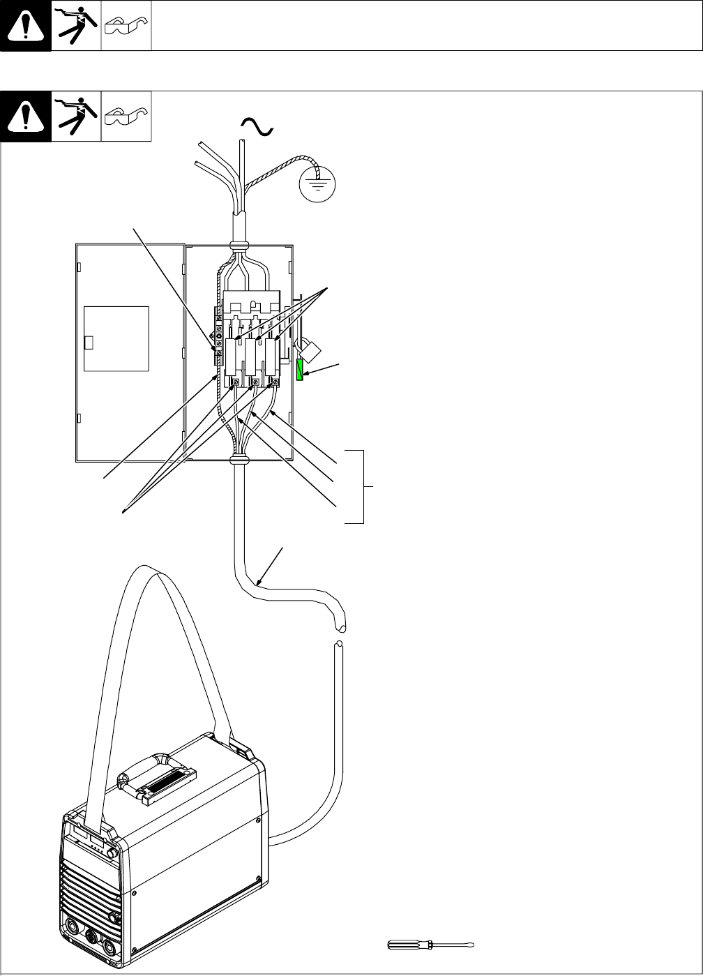
For Three-Phase Operation
1 Input Power Cord.
2 Disconnect Device (switch shown in
the OFF position)
3 Green Or Green/Yellow Grounding
Conductor
4 Disconnect Device Grounding
Terminal
5 Input Conductors (L1, L2 And L3)
6 Disconnect Device Line Terminals
Connect green or green/yellow grounding
conductor to disconnect device grounding
terminal first.
Connect input conductors L1, L2, and L3
to disconnect device line terminals.
7 Over-Current Protection
Select type and size of over-current
protection using Section 4-9 (fused dis-
connect switch shown).
Close and secure door on disconnect de-
vice. Remove lockout/tagout device, and
place switch in the On position.
= GND/PE Earth Ground
L1
2
1
L2
L3
3
3
4
5
6
7
Tools Needed:
A. Connecting Three-Phase Input Power