


. Complete Parts List available at www. MillerWelds.com
OM-228 042 Page 16
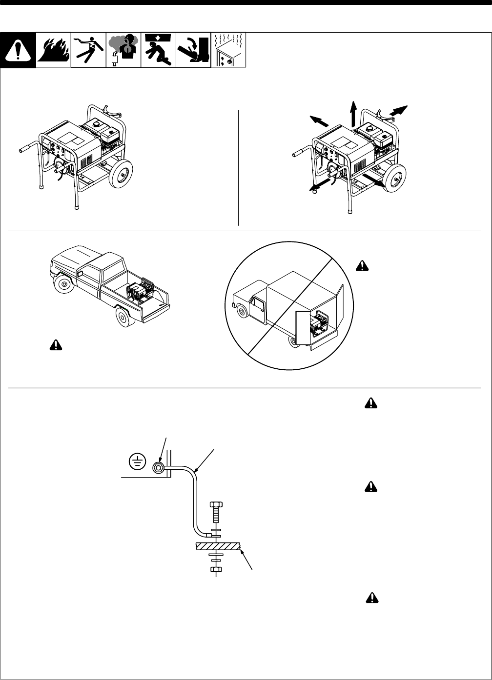
SECTION 5 − INSTALLATION
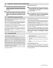
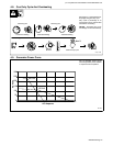
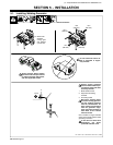
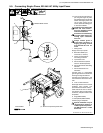
Always ground generator
frame to vehicle frame to pre-
vent electric shock and static
electricity hazards.
1 Metal Vehicle Frame
2 Equipment Grounding
Terminal
3 Grounding Cable
Bed liners, shipping skids,
and some running gear insu-
late the welding generator
from the vehicle frame. Al-
ways connect a ground wire
from the generator equip-
ment grounding terminal to
bare metal on the vehicle
frame as shown.
Use #10 AWG or larger insulated
copper wire to make metal-to-metal
grounding connection.
If unit does not have GFCI
receptacles, use GFCI-
protected extension cord.
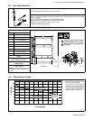
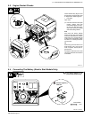
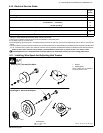
5-1. Installing Welding Generator
Ref. install 11/02 − Ref. 800 652 / 804 476-C / S-0854
18 in
(460 mm)
18 in
(460 mm)
18 in
(460 mm)
18 in
(460 mm)
18 in
(460 mm)
Movement
Airflow Clearance
Location
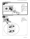
. Shown with
standard
running gear
and optional
cylinder rack.
Always securely fasten welding
generator onto transport vehicle
or trailer and comply with all DOT
and other applicable codes.
GND/PE
2
3
1
Do not install unit where air
flow is restricted or engine
may overheat.