


. Complete Parts List available at www. MillerWelds.com
OM-228 042 Page 21
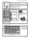
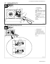
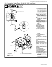
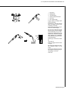
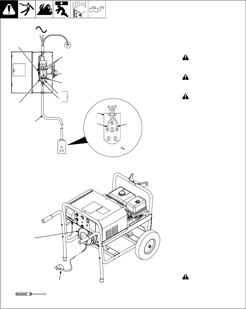
5-9. Connecting Single−Phase, 230 Volt AC Utility Input Power
. This unit can provide weld out-
put using the engine to power
the welding power source/wire
feeder OR single−phase 230
volt ac utility power can be
used to power the welding pow-
er source/wire feeder.
Installation must meet all Na-
tional and Local Codes −
have only qualified persons
make this installation.
Disconnect and lockout/tag-
out input power before con-
necting input conductors
from unit.
Always connect green or
green/yellow conductor to
supply grounding terminal
first, and never to a line ter-
minal.
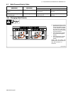
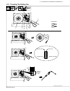
1 Rating Label
Supply correct input power.
2 Black And White Input
Conductor (L1 And L2)
3 Green Or Green/Yellow
Grounding Conductor
4 Input Power Cord.
5 Disconnect Device (switch
shown in the OFF position)
6 Disconnect Device Grounding
Terminal
7 Disconnect Device Line
Terminals
Connect green or green/yellow
grounding conductor to disconnect
device grounding terminal first.
Connect input conductors L1 and
L2 to disconnect device line termi-
nals.
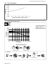
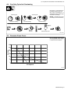
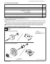
8 Over-Current Protection
Select type and size of over-current
protection using Section 5-10
(fused disconnect switch shown).
Close and secure door on discon-
nect device. Remove lockout/tag-
out device, and place switch in the
On position.
9 Plug (NEMA 6-50P)
10 Receptacle (NEMA 6-50R)
Connect plug to receptacle.
Special installation may be
required where gasoline or
volatile liquids are present −
see NEC Article 511 or CEC
Section 20.
Ref. 802 085 / Ref. 803 766-B / 804 476-C
1
L1
L2
9
230 VAC, 1
10
Tools Needed:
5
4
L1
L2
1
=GND/PE Earth Ground
3
2
6
7
8
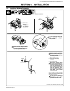
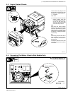
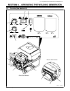
. Shown with optional cylinder rack