


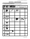
. Complete Parts List available at www. MillerWelds.com
OM-228 042 Page 27
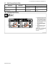
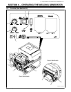
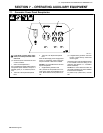
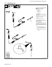
6-2. Description Of Controls (See Section 6-1)
1 Engine Switch
Use switch to control ignition circuit.
For Recoil Start: Turn switch to On position
when starting engine. Turn switch to Off posi-
tion to stop engine. Engine cannot be started
with switch in the Off position.
For Electric Start: Turn switch to Start position
when starting engine. Switch returns to Run
position when engine starts. Turn switch to Off
position to stop engine.
Engine stops if oil level is too low. Engine can-
not be restarted until sufficient oil is added.
2 Low Oil Pressure Light
Light goes on and engine stops if engine oil
level is too low.
Engine cannot be restarted until sufficient oil
is added.
NOTICE − Stop engine and add oil if light
goes on (see Section 5-3).
3 Starter Handle
4 Choke Control
Use control to change engine air/fuel mix.
Move control to far right if starting a cold en-
gine. Move control to far left if starting a warm
engine.
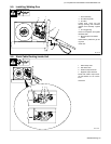
To Start:
D Open fuel valve (see Section 5-3).
D Set choke.
D For Recoil Start: Turn Engine switch to
On and pull starter handle.
D For Electric Start: Turn Engine switch to
Start. When engine starts, allow switch
to return to Run position.
D Open choke as engine warms.
NOTICE − If the engine does not start, let
engine come to a complete stop before at-
tempting restart.
To Stop:
D Turn Engine switch to Off.
. Always close fuel valve after stopping
unit. Moving unit with fuel valve open may
cause carburetor flooding and make
starting difficult.
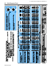
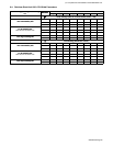
5 Wire Speed Control
Turn control clockwise to increase wire feed
speed. (see weld parameter chart in welding
power source or Section 6-3).
6 Voltage Control
Turn control clockwise to increase voltage
(see weld parameter chart in welding power
source or Section 6-3).
7 Gun Trigger Receptacle
8 Wall/Generator Switch
Use switch to select source of power for weld-
ing power source.
Place switch in Generator position for welding
power source to run on generator input power.
Place switch in Wall position for the welding
power source to run on utility power. Place
switch in Off position before connecting to util-
ity power.
. With switch in the Wall position and the
generator not running, the auxiliary power
receptacles do not work.
9 Over Temperature Light
Light flashes when unit has overheated and
weld output is not available. Allow fan to run to
cool unit. When light goes out, unit is ready for
service.