


OM-1500-19 Page 16
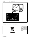
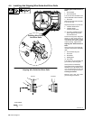
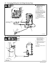
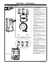
4-4. Installing And Aligning Wire Guide And Drive Rolls
Ref. 804 001-B
Installing Wire Guide And Drive
Rolls:
1 Drive Roll Nut
2 Drive Roll Carrier
Turn nut one click until lobes of nut
line up with lobes of drive roll carrier.
3 Drive Roll
Slide drive roll onto drive roll carrier.
Turn nut one click.
Repeat procedure for top drive roll.
4 Inlet Wire Guide Screw
5 Inlet Wire Guide
(One Piece Anti-wear)
. The factory installed inlet wire
guide is good for up to 5/64
inch diameter wire.
Loosen securing screw. Align inlet
guide so inlet guide screw is
centered in groove in guide, or so tip
is as close to drive rolls as possible
without touching. Tighten screw.
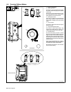
Aligning Wire Guide And Drive
Rolls:
View is from top of drive rolls look-
ing down with pressure assembly
open.
6 Drive Roll Securing Nut
7 Drive Roll
8 Wire Guide
9 Welding Wire
10 Drive Gear
Turn screw in or out until drive roll
groove lines up with wire guide.
Close pressure roll assembly.
Only bottom drive roll alignment is
adjustable. Turn adjustment screw
in or out until groove in drive roll
lines up with wire guide as shown.
Cleaning Drive Rolls:
Remove drive rolls, and clean
grooves using a wire brush.
Tools Needed:
3/16 in
Aligning Wire Guide And Drive Rolls
2
3
4
5
Installing Wire Guide
And Drive Rolls
1
Correct Incorrect
8
7
6
10
9