


OM-1500-19 Page 20
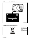
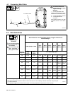
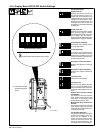
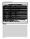
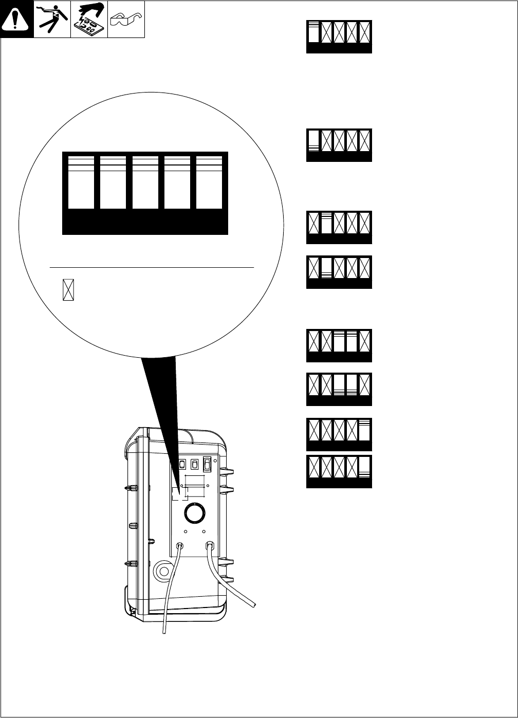
4-10. Display Board (PC20) DIP Switch Settings
DIP Switch Factory Settings
Ref. 804 006-A
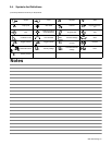
DIP Switch Settings:
Display Hold ON
Displays will hold their last value for
five seconds after the trigger is re-
leased. After the hold times out, the
Voltage Display will show open circuit
voltage. If the Wire Speed / Amps
Display is set to display Amps, the
amperage value will hold, after the
hold times out, preset Wire Speed will
be displayed.
Display Hold OFF
Displays will not hold values. Immedi-
ately, when the trigger is released,
the Voltage Display will show open
circuit voltage. The Wire Speed /
Amps Display will display preset Wire
Speed when the trigger is released.
Do Not Display Amperage
Wire Speed / Amps Display will dis-
play only Wire Speed.
Display Amperage
Wire Speed / Amps Display will dis-
play Amps while welding and Wire
Speed while not welding. If the hold
function is enabled, Amps will be dis-
played during hold also.
Wire Speed - Inches Per Minute
Displays Wire Speed in Inches per
Minute.
Wire Speed - Meters Per Minute
Displays Wire Speed in Meters per
Minute.
Information OFF
Information is not displayed.
Information ON
With switch in ON position, at feeder
power up, feeder will display various
sets of information. Each set of infor-
mation will be displayed for three sec-
onds.
Display Board (PC20) Software
Part Number −
Top display will show the first three
digits, bottom display will show last
three digits of the Display board
(PC20) software revision level.
Motor Board (PC1) Software Part
Number −
Top display will show the first three
digits, bottom display will show last
three digits, of the Motor board (PC1)
software revision level.
Accumulated Weld Time −
This is the time the feeder has actual-
ly been used for welding. This infor-
mation will be displayed in two
halves. First being years and days,
second in hours and minutes. Top
display will show years/hours, bot-
tom display will show days/minutes.
Indicates Switch does not Affect This Function
1 2 3 4 5
1 2 3 4 5
1 2 3 4 5
1 2 3 4 5
1 2 3 4 5
1 2 3 4 5
1 2 3 4 5
1 2 3 4 5
1 2 3 4 5
. DIP switch is located
behind front panel as
shown.