


OM-1500-19 Page 18
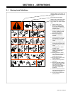
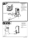
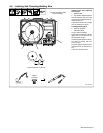
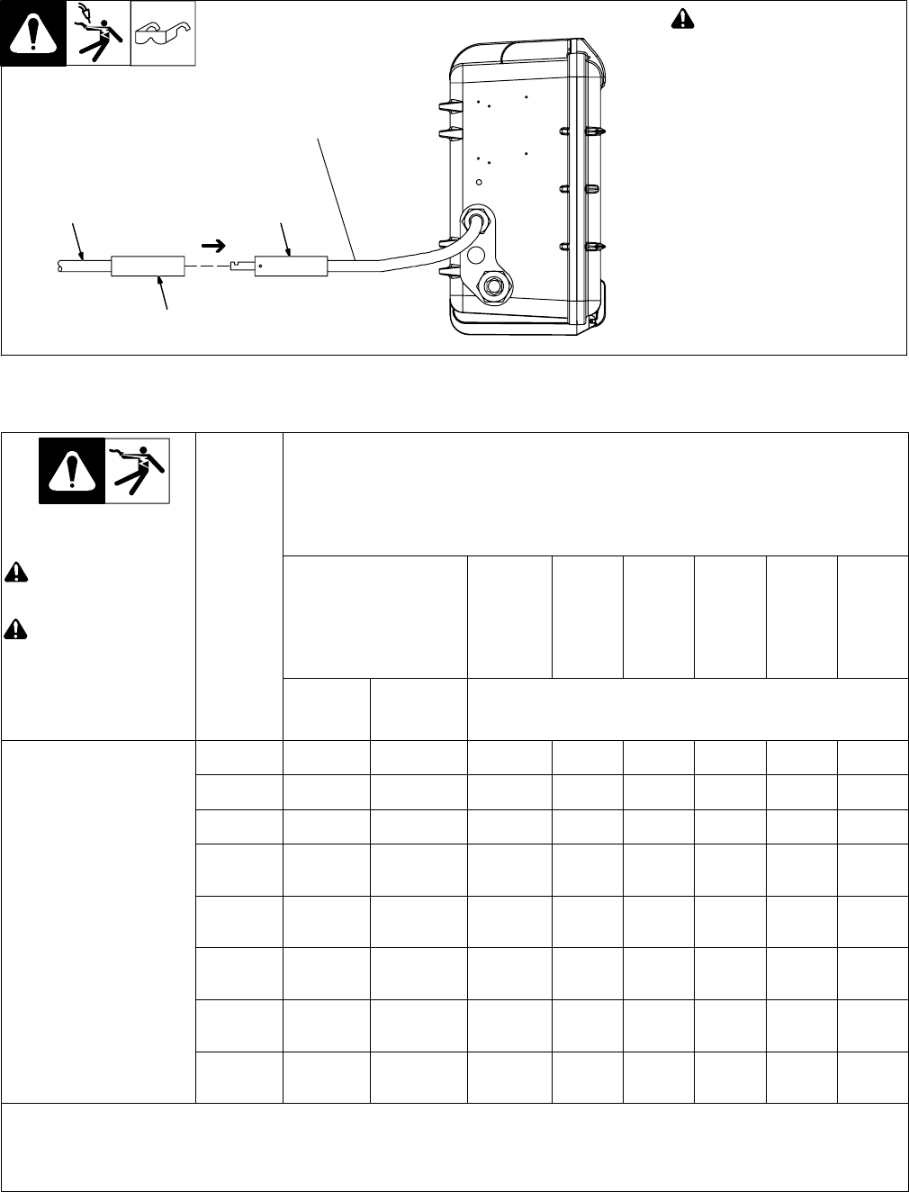
4-7. Connecting Weld Cable
! Turn Off wire feeder and
welding power source. Stop
engine on welding
generator.
1 User-Suppled Weld Cable
Follow wire manufacturer’s recom-
mendations for weld cable polarity.
2 User-Suppled Male Connector
3 User-Suppled Female
Connector
Push female connector over male
connector, and turn 1/4 turn clock-
wise.
804 004-A
2
1
3
From Wire Feeder
Rear View
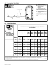
4-8. Weld Cable Sizes
Weld Output
Terminals
Weld Cable Size** and Total Cable (Copper) Length in Weld Circuit
Not Exceeding***
! Turn off power before
connecting to weld out-
put terminals.
! Do not use worn, dam-
aged, undersized, or
poorly spliced cables.
100 ft (30 m) or Less
150 ft
(45 m)
200 ft
(60 m)
250 ft
(70 m)
300 ft
(90 m)
350 ft
(105 m)
400 ft
(120 m)
Welding
Amperes
10 − 60%
Duty
Cycle
60 − 100%
Duty
Cycle
10 − 100% Duty Cycle
100 4 (20) 4 (20) 4 (20) 3 (30) 2 (35) 1 (50) 1/0 (60) 1/0 (60)
150 3 (30) 3 (30) 2 (35) 1 (50) 1/0 (60) 2/0 (70) 3/0 (95) 3/0 (95)
200 3 (30) 2 (35) 1 (50) 1/0 (60) 2/0 (70) 3/0 (95) 4/0 (120) 4/0 (120)
250 2 (35) 1 (50) 1/0 (60) 2/0 (70) 3/0 (95) 4/0 (120)
2 ea. 2/0
(2x70)
2 ea. 2/0
(2x70)
300 1 (50) 1/0 (60) 2/0 (70) 3/0 (95) 4/0 (120)
2 ea. 2/0
(2x70)
2 ea. 3/0
(2x95)
2 ea. 3/0
(2x95)
350 1/0 (60) 2/0 (70) 3/0 (95) 4/0 (120)
2 ea. 2/0
(2x70)
2 ea. 3/0
(2x95)
2 ea. 3/0
(2x95)
2 ea. 4/0
(2x120)
400 1/0 (60) 2/0 (70) 3/0 (95) 4/0 (120)
2 ea. 2/0
(2x70)
2 ea. 3/0
(2x95)
2 ea. 4/0
(2x120)
2 ea. 4/0
(2x120)
500 2/0 (70) 3/0 (95) 4/0 (120)
2 ea. 2/0
(2x70)
2 ea. 3/0
(2x95)
2 ea. 4/0
(2x120)
3 ea. 3/0
(3x95)
3 ea. 3/0
(3x95)
* This chart is a general guideline and may not suit all applications. If cable overheats, use next size larger cable.
**Weld cable size (AWG) is based on either a 4 volts or less drop or a current density of at least 300 circular mils per ampere.
( ) = mm
2
for metric use S-0007-F−
***For distances longer than those shown in this guide, call a factory applications representative at 920-735-4505.