


OM-486 Page 9
SECTION 2 – DEFINITIONS
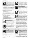
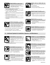
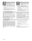
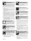
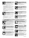
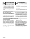
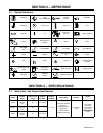
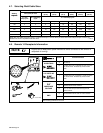
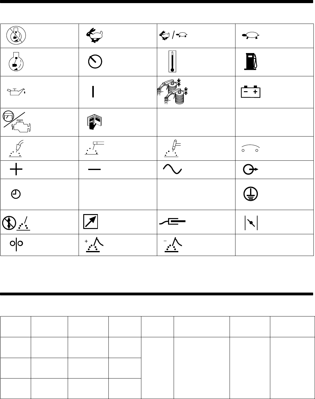
2-1. Symbol Definitions
Stop Engine
Fast
(Run, Weld/Power)
Fast/Slow
(Run/Idle)
Slow (Idle)
Start Engine Panel/Local Temperature Fuel
Engine Oil On
Check Valve
Clearance
Battery (Engine)
Engine
Read Operator’s
Manual
A
Amperes
V
Volts
MIG (GMAW),
Wire
Stick (SMAW) TIG (GTAW) Circuit Breaker
Positive Negative
Alternating Current
(AC)
Output
Time
h
Hours
s
Seconds
Protective Earth
(Ground)
Do not switch while
welding
14
Remote 14
Receptacle
Work Connection Engine Choke
Wire Feed
Electrode
Positive
Electrode Negative
SECTION 3 – SPECIFICATIONS
3-1. Weld, Power, And Engine Specifications
Welding
Mode
Rated
Welding
Output
Maximum
Open-Circuit
Voltage
Amperage
Range In
CC Mode
Voltage
Range In
CV Mode
Auxiliary
Power Rating
Fuel
Capacity
Engine
CC/DC
250 A, 25 V,
100% Duty
Cycle
80 40 – 250 A
Continuous: 8 kVA/kW,
Onan P220
CV/DC
250 A, 25 V,
100% Duty
Cycle
50 – –
10 – 40 V
66.6/33.3 A,
120/240 V AC, 60 Hz,
Single-Phase,
10 gal (38 L)
Tank
Air-Cooled,
Two-Cylinder,
Four-Cycle,
20 HP Gasoline
CC/AC
200 A, 25 V,
60% Duty
Cycle
75 40 – 200 A
Peak: 9 kVA/kW
(w/Weld Contactor Off)
20 HP Gasoline
Engine