


OM-486 Page 18
SECTION 5 – OPERATING WELDING GENERATOR
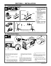
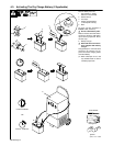
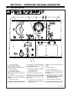
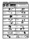
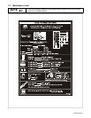
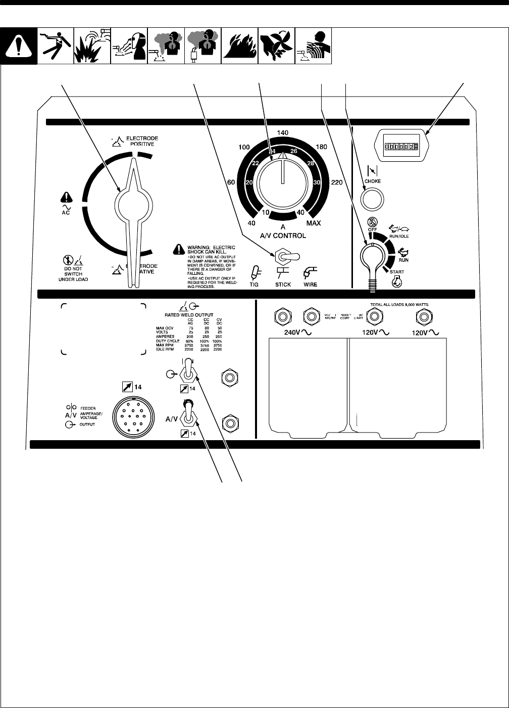
5-1. Front Panel Controls
Ref. ST-189 925-A
1 DC Polarity/AC Switch
Y Do not switch under load.
Use switch to select AC weld output or polar-
ity of DC weld output.
2 Process Select Switch
Y Do not switch under load.
Use switch to select output for weld process.
3 A/V Control
Use control to select weld voltage or
amperage. Control may be adjusted while
welding.
4 Engine Control Switch
Use switch to start engine, select speed, and
stop engine. In Run/Idle position, engine
runs at idle speed at no load, and weld/power
speed under load. In Run position, engine
runs at weld/power speed.
. Place switch in Run position to operate
most GMAW equipment.
5 Engine Choke Control
Use control to change engine air-fuel mix.
To Start: pull out choke and turn Engine
Control switch to Start position. Release
switch and slowly push choke in when
engine starts.
. If the engine does not start, let the
engine come to a complete stop before
attempting restart.
To Stop: turn Engine Control switch to Off
position.
6 Engine Hour Meter
7 Output (Contactor) Switch
Use switch to control remote contactor if
connected to remote 14 receptacle RC1
(see Section 5-2).
Y Weld output terminals are energized
when Output (Contactor) switch is
On and engine is running.
8 Remote Amperage/Voltage Switch
Use switch to select front panel or remote
amperage/voltage control (see Section 5-2).
421
8
563
7