


OM-486 Page 29
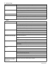
B. Auxiliary Power
Trouble Remedy
No power output. Reset circuit breakers CB1, CB2, CB3 and/or CB4 (see Section 6-1).
Check fuse F1, and replace if necessary (see Section 7-7).
Have Factory Authorized Service Agent check brushes, slip rings, and field current control board PC2.
Low power output. Check and clean air cleaner as necessary.
Check and adjust engine speed (see Section 7-6).
See engine manual.
High power output. Check and adjust engine speed (see Section 7-6).
Erratic power output. Have Factory Authorized Service Agent check brushes, slip rings, and field current control board PC2.
Check receptacle wiring and connections.
Check governor according to engine manual.
C. Engine
Trouble Remedy
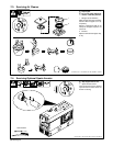
Engine will not crank. Check fuse F6, and replace if open (see Section 7-7).
Check battery voltage.
Check battery connections and tighten if necessary.
Check plug PLG5 and plug PLG8 connections.
Have Factory Authorized Service Agent check Engine Control switch S5.
Engine does not start. Check fuel level (see Section 4-2).
Check battery and replace if necessary.
Check engine charging system according to engine manual.
See engine manual.
Engine starts but stops when Engine
Control switch returns to Run position.
Check oil level (see Section 4-2).
Check and refill crankcase with proper viscosity oil for operating temperature, if necessary (see Sec-
tion 7-2).
Have Factory Authorized Service Agent check low oil pressure shutdown switch S5.
Battery discharges between uses. Clean top of battery with baking soda and water solution; rinse with clear water.
Periodically recharge battery (approximately every 3 months).
Replace battery.
Check voltage regulator according to engine manual.
Engine stopped during normal
operation.
Check fuel level (see Section 4-2).
Check oil level (see Section 4-2).
Have Factory Authorized Service Agent check low oil pressure shutdown switch S5.
Engine does not return to idle speed. Be sure Engine Control switch S2 is in Run/Idle position.
Remove all weld and auxiliary power loads.
Turn off remote device connected to Remote 14 receptacle RC1 (see Section 4-8).
Check for obstructed movement of solenoid linkage (see Section 7-6).
Have Factory Authorized Service Agent check idle module PC1 and current transformer CT1.
Engine does not remain at weld/power
speed when power or weld load is
applied with Engine Control switch in
Run/Idle position.
Place Engine Control switch in the Run position for small loads.